The Crane Limits and Appearance window ( enabled , not read-only)
Method 1 : Home > Project Settings > Fabricator > Crane Limits and Appearance .
Method 2, 3 & 4 : In Modeling or the Drawing Editor , choose Settings > Fabricator Settings > Crane Limits and Appearance . (classic), or use a keyboard shortcut , or click the icon.
Also see :
- Capacity limit (uses as a default the " Lift capacity limit " set on this window)
page 1 | contents | home > profect settings > fabricator > | classic | top
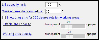
Lift capacity limit: The percentage that is the default " Capacity limit " for a crane that is newly added using Add Crawler Crane or Add Tower Crane .
Example: You enter 90% as the " Lift capacity limit " here, on the Crane Setup window. You then Add Crawler Crane and, on the Crane Placement window, press the " Lift Config " button. On the Lift Configuration window for the new crawler crane, you will find that the " Capacity limit " is 90%. You can change that " Capacity limit " if you so choose.
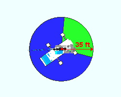
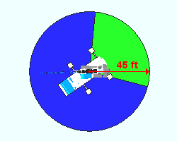
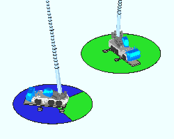
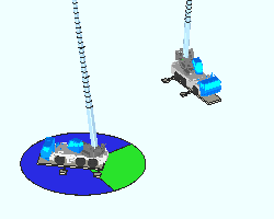
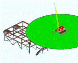
Working area diagram radius: The radius of the working area shown on a crane placement's working area diagram. A working area is a configuration of a truck or crawler crane's lower works that determines its quadrants of operation. A working area diagram shows these quadrants extended to the radius that you choose.
|
||
| A working area diagram radius is measured from the center of a crane placement. |
Note 1: Some working areas consist of a single 360 degree quadrant. Such diagrams are visible only when " Show diagram for 360 degree rotation working areas " is checked (
).
Note 2: When the project's primary dimension " Units " are imperial (that is, set to ' Imperial (ft-in)' or ' Imperial (inches-sixteenths)' or etc.), this radius is expressed in feet. When the primary dimension " Units " are set to ' Metric ', this radius is expressed in meters. In either case, the radius is always expressed as a whole or decimal number.
Note 3: A truck crane's quadrants are defined under " Working Areas " on the Truck Crane Specification window. A crawler crane's quadrants are defined under " Working Areas " on the Crawler Crane Specification window. " Working Area " on the Lift Configuration window lets you define the quadrant of operation that is to be used for a particular lift. Working areas are not configured for tower cranes; consequently, working area diagrams are never shown for their placements.
Show diagram for 360 degree rotation working areas: ![]() or
or ![]() . This applies to truck or crawler crane placements with a single 360 degree quadrant.
. This applies to truck or crawler crane placements with a single 360 degree quadrant.
|
||
| "Show diagram" has no effect on placements of cranes that have two or more quadrants in their working areas. |
If this box is checked (
), a working area diagram is shown under all truck and crawler crane placements visible in your Modeling view.
If the box is not checked (
), no working area diagram is shown for placements of cranes that that have a single 360 degree quadrant.
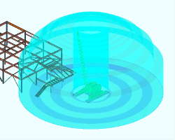
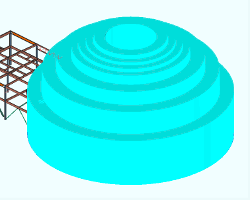
Liftable shell opacity: Any level from 0 (transparent) to 100 (opaque). The liftable shell is the dome that is displayed when you left-click a crane in your Modeling view.
|
|
|
the slider sets the level |
|
||
| The "dome" around the crane placement represents the reach of the crane's boom. The center cylinder is the no-lift zone around the crane. The alternating dark and light bands are each 10 ft in width. |
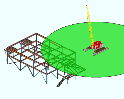
Working area opacity: Any level from 0 (transparent) to 100 (opaque). This applies to working area diagrams shown for truck and crawler crane placements.
|
|
|
the slider sets the level |
|
||
| When a working area is opaque, member main and member connection material cannot be seen through it. |
page 1 | contents | home > project settings > fabricator > | classic | top
