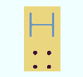
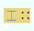
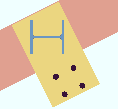
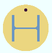
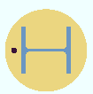
The Advanced Base / Cap Plate Options window
|
Options on this window correlate to connection design locks in leaves named " Additional Holes " and " Left Base Plate Extension " ( |
Options :
|| Left || Right || Additional Holes || top || Bottom || Round Plate Holes || Drain/Vent Holes ||
base / cap plate schedule | top
To open Advanced Base / Cap Plate Options :
- Press the " More... " button that is to the right of a line on the Base / Cap Plate Schedule .
base / cap plate schedule | top
![]() " Copy " " Paste " " Save " " Load " buttons
" Copy " " Paste " " Save " " Load " buttons
base / cap plate schedule | top
| || Left || Right || Additional Holes || top || Bottom || Round Plate Holes || Drain/Vent Holes || |
|
|||||||||
Connection design locks: "
Left Base Plate Extension "
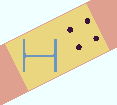
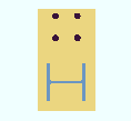
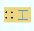
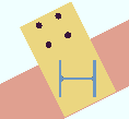
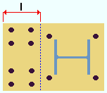
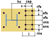
Leg length: The distance (in the primary dimension " Units " or other units ) from where the left edge of the base plate would be if there was no left leg to the "left" edge of the left leg.
|
l = leg length |
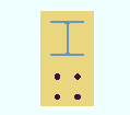
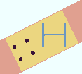
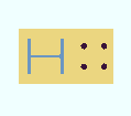
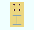
Note: The left of the base/cap plate is on the left when the " Column rotation " is ' 0 ' and the " Plate rotation " is ' 0 ' and the column does not frame to a beam or support a joist. See the illustrations above.
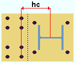
Horizontal to first column of holes: The distance parallel with the " Leg length " (in the appropriate " Units ") from the center of the base/cap plate to the first column of holes in the left leg.
|
hc = horizontal to first column of holes |
The center of a base/cap plate is the center of the plate's " Length " and " Width " defined on the Base / Cap Plate Schedule . It is the true center of the plate if all fields under all tabs on this window are ' 0 '.
This distance is measured horizontally when the " Column rotation " is ' 0 ' and the " Plate rotation " is ' 0 '. Otherwise, the distance may be measured at an angle.
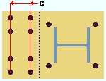
Columns of holes: The quantity of columns of holes.
|
c = columns of holes |
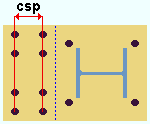
Column spacing: The center-to-center distance (in the primary dimension " Units " or other units ) between columns of holes.
|
csp = column spacing |
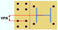
Vertical to first hole NS: The distance perpendicular to the " Leg length " (in the appropriate " Units ") from the center of the base/cap plate to the first row of holes in the near side of the left leg.
|
vns = vertical to first hole NS |
The near side of the base/cap plate is the near side of the column when the " Column rotation " is ' 0 ' and the " Plate rotation " is ' 0 '.
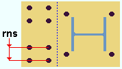
Rows of holes NS: The quantity of rows of holes.
|
rns = rows of holes NS |
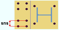
Row Spacing NS: The center-to-center distance (in the primary dimension " Units " or other units ) between rows of holes.
|
sns = row spacing NS |
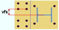
Vertical to first hole FS: The distance perpendicular to the " Leg length " (in the appropriate " Units ") from the center of the base/cap plate to the first row of holes in the far side of the left leg.
|
vfs = vertical to first hole FS |
The far side of the base/cap plate is the far side of the column when the " Column rotation " is ' 0 ' and the " Plate rotation " is ' 0 '.
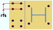
Rows of holes FS: The quantity of rows of holes.
|
rfs = rows of holes FS |
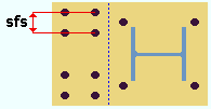
Row spacing FS: The center-to-center distance (in the primary dimension " Units " or other units ) between rows of holes.
|
sfs = row spacing FS |
base / cap plate schedule | top
| || Left || Right || Additional Holes || top || Bottom || Round Plate Holes || Drain/Vent Holes || |
|
|||||||||
| l = leg length hc = horizontal to first column of holes c = columns of holes csp = column spacing vns = vertical to first hole NS rns = rows of holes NS sns = row spacing NS vfs = vertical to first hole FS rfs = rows of holes FS sfs = row spacing FS |
|
Connection design locks: "
Right Base Plate Extension "
base / cap plate schedule | top
| || Left || Right || Additional Holes || top || Bottom || Round Plate Holes || Drain/Vent Holes || |

Hole type: None or Grout or Vent/Drain or Standard round or Oversized round or Cope hole or Anchor bolt hole or Plug weld hole .
' None ' prevents an additional hole from being generated by this particular line in the " Additional Holes " tab.
' Grout ' designates a grout hole, which is for pouring grout under a base plate. By default, grout holes are not matchable ("
Matchable ").
' Vent/Drain ' designates a vent hole or drain hole for galvanizing. When you select this type of hole, the " Hole diameter " resets to the value that is specified as the " Default vent/drain hole diameter " on the Galvanizing Settings window. By default, vent/drain holes not matchable ("
Matchable ").
' Standard round ' designates a standard round hole. A standard round hole is, by default, matchable ("
Matchable ").
' Oversized round ' designates an oversized round hole. An oversized round is, by default, matchable ("
Matchable "). The matched hole will be standard round.
' Cope hole ' designates a cope hole. By default, cope holes are not matchable ("
Matchable ").
' Anchor bolt hole ' designates a hole for an anchor bolt. An anchor bolt holes is, by default, matchable ("
Matchable ").
' Plug weld hole ' designates a plug weld hole. By default, plug weld holes are not matchable ("
Matchable ").
Connection design locks: "
Additional Holes "
Bolt diameter: The diameter of the bolt (in the primary dimension " Units " or other units ).
Bolts may be generated automatically if this "additional hole" is in a user base/cap plate that frames to a beam's top or bottom flange. If the specified " Hole type " for this hole is set to be "
Matchable ,".the matching holes phase of Create Solids automatically matches this hole to the beam and generates a bolt through this hole and the matched hole. The bolt will be the " Bolt diameter " that is specified here.
Connection design locks: "
Additional Holes "
Hole diameter: The diameter of the hole (in the primary dimension " Units " or other units ). A diameter of zero (' 0 ') designates a CNC mark .
Connection design locks: "
Additional Holes "
X coordinate: A positive or negative distance (in the primary dimension " Units " or other units ).
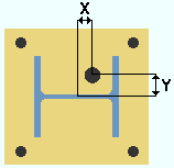
X = X coordinate. This example shows a column whose " Plate rotation " is zero, whose " Column rotation " is zero, whose " Offset parallel to web " is zero, and whose " Offset parallel to flange " is zero. The center of such a column coincides with the center of the user base plate. The center of a user base / cap plate is the center of its " Length " and " Width ," which are defined on the Base / Cap Plate Schedule .
An additional hole's " X coordinate " is measured parallel with the plate's " Length " from the center of the base/cap plate to the center of the hole.
Assuming that the column's " Plate rotation " is zero, the following is true:
If the column frames to nothing (" Indeterminate end "), the " X coordinate " dimension is parallel with the column web. For a column in a plan view whose " Column rotation " is zero, a positive distance would place the "additional hole" to the right of the center of the user base / cap plate, while a negative distance would place the "additional hole" to the left of the plate's center.
If the column frames to a beam or joist, this dimension is parallel with the work line of the beam or joist.
Connection design locks: "
Additional Holes "
Y coordinate: A positive or negative distance (in the primary dimension " Units " or other units ).

Y = Y coordinate. This example shows a column whose " Plate rotation " is zero, whose " Column rotation " is zero, whose " Offset parallel to web " is zero, and whose " Offset parallel to flange " is zero. The center of such a column coincides with the center of the user base plate. The center of a user base / cap plate is the center of its " Length " and " Width ," which are defined on the Base / Cap Plate Schedule .
The additional hole's " Y coordinate " is measured parallel with the plate's " Width " from the center of the base/cap plate to the center of the hole.
Assuming that the " Plate rotation " is zero, the following is true:
If the column frames to nothing (" Indeterminate end "), the " Y coordinate " dimension is perpendicular to the column web. For a column in a plan view whose " Column rotation " is zero, a positive distance places the "additional hole" above the center of the user base / cap plate, while a negative distance places the "additional hole" below the plate's center.
If the column frames to a beam or joist , this dimension is perpendicular to the work line of the beam or joist.
Connection design locks: "
Additional Holes "
base / cap plate schedule | top
| || Left || Right || Additional Holes || Top || Bottom || Round Plate Holes || Drain/Vent Holes || |
|
|||||||||
| l = leg length
vc = vertical to first column of holes r = rows of holes rs = row spacing ns = horizontal to first hole NS cns = columns of holes NS sn = column spacing NS fs = horizontal to first hole FS cfs = columns of holes FS sf = column spacing FS |
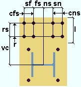
|
Connection design locks: "
Top Base Plate Extension "
base / cap plate schedule | top
| || Left || Right || Additional Holes || top || Bottom || Round Plate Holes || Drain/Vent Holes || |
|
|||||||||
| l = leg length
vc = vertical to first column of holes r = rows of holes rs = row spacing ns = horizontal to first hole NS cns = columns of holes NS sn = column spacing NS fs = horizontal to first hole FS cfs = columns of holes FS sf = column spacing FS |
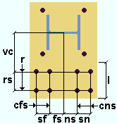
|
Connection design locks: "
Bottom Base Plate Extension "
base / cap plate schedule | top
| || Left || Right || Additional Holes || top || Bottom || Round Plate Holes || Drain/Vent Holes || |
Hole count: Any number of holes that is equal to 360 divided by the " Degrees between holes ." This is the total number of holes in the ' Round ' plate.
| Hole count | 360 / count | Degrees between holes |
| 1 | 360 | 360 |
| 2 | 180 | 180 |
| 3 | 120 | 120 |
| 4 | 90 | 90 |
| 5 | 72 | 72 |
Degrees between holes: The number of degrees of separation between each adjacent hole in the ' Round ' plate. Since holes in the circular pattern must be equally spaced, the " Degrees between holes " multiplied by the " Hole count " must equal 360.
360 degrees
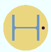 |
180 degrees
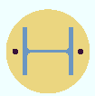 |
120 degrees
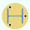 |
90 degrees
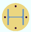 |
Tip: If you set the " Hole count " then Tab out of this field, Advanced Base / Cap Plate Options automatically calculates this value by dividing 360 degrees by the hole count, thus ensuring that all of the holes are evenly spaced.
Warning: If you enter a number of degrees that when divided into 360 gives you a whole number other than the " Hole count ," Advanced Base / Cap Plate Options will change the " Hole count ."
Radius: A distance (in the primary dimension " Units " or other units ). The center of a round column plate is the center of the " Diameter " defined on the Base / Cap Plate Schedule . The " Radius " is the distance from the center of the ' Round ' plate to the center of any hole in the circular hole group. All holes in the circular hole group will be this distance from the center.
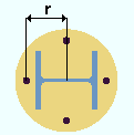
|
r = radius |
Warning: The distance you enter here must be less than half the " Diameter " of the plate.
Pattern angular offset: The number of degrees that you want each hole in the ' Round ' plate to be offset in a counterclockwise direction.
|
|||
| The effect of changing the " Pattern angular offset " for a one-hole round base plate on a column in a plan view whose " Column rotation " and " Plate rotation " are both zero. |
base / cap plate schedule | top
| || Left || Right || Additional Holes || top || Bottom || Round Plate Holes || Drain/Vent Holes || |
For all patterns ( pipe , tube , wide flange ):
Only one pattern, or " None ," can be selected at a time .
The " Offset parallel to web " " Offset parallel to flange " and " Section size " that is entered here should match the " Offset parallel to web " " Offset parallel to flange " and " Section size " on the Column Edit window. The " Plate rotation " entered here should be the negative of the " Plate rotation " entered on the Column Edit window. This applies to all patterns.
Certain drain/vent hole patterns are implemented using system-applied Fit operations. If you edit such a column plate's material and, for example, change its thickness, the pattern on that particular instance of the plate will be discarded.
Status Display: Material status > Material fitted, mitred or coped .
Material Edit Warning: Cut or fit operation will be lost
Drain/vent hole patterns for pipe ( HSS round ):
| 1 | 2 | 3 | 4 | 5 | 6 | 7 |

|
||||||
When a " Section size " is entered here for a selected pattern, the " Pipe thickness " ( read-only ) and " Pipe diameter " ( read-only ) and " Pipe inner diameter " values are automatically filled out, based on information stored in the local shape file . This applies to all pipe patterns. The " Pipe inner diameter " can be changed for any of these patterns, for example, to make the pattern smaller.
read-only read-only read-onlyThe " Total area " ( read-only ) " Area removed " ( read-only ) and " Percent removed " ( read-only ) are calculated for pattens 2 , 3 , 4 , 6 , 7 based on the selected pattern, any user-entered values such as " Pipe inner diameter ," and on the " Section size " information maintained in the local shape file .
A " Slot width " can be entered for pattern 2 , 5 , 7 . A " Slot length " can be entered for pattern 6 . A " Half circle radius " can be entered for pattern 3 .
" Pattern rotation " allows entry of a number of degrees of rotation for patterns 2 , 3 , 4 , 6 , 7 .
" This vent/drain opening on the pipe will not be created by the system "
is a message that appears for pattern 5 . This means that, for this pattern, you manually have to add the hole yourself.
Drain/vent hole patterns for tube ( HSS rectangular ):
| 1 | 2 | 3 | 4 |

|
|||
When a " Section size " is entered here for a selected pattern, the " Tube thickness " ( read-only ) and " Tube width " ( read-only ) and " Tube Length " ( read-only ) are automatically filled out, based on information stored in the local shape file . This applies to all tube patterns.
read-only read-only read-onlyThe " Total area " ( read-only ) " Area removed " ( read-only ) and " Percent removed " ( read-only ) are calculated for pattens 2 , 3 , 4 based on the selected pattern, any user-entered values such as " Tube inner width ," and on the " Section size " information maintained in the local shape file .
A " Tube corner radius " " Tube inner width " and " Tube inner length " can be entered for pattens 1 , 2 , 3 , 4 . A " Hole diameter " can be entered for pattern 2 . A " Triangle leg length " can be entered for pattern 3 , 4 . " Flip corners " can be turned on (
) or turned off (
) for pattern 4 .
Drain/vent hole patterns for wide flange:
| 1 | 2 |

|
|
When a " Section size " is entered here for a selected pattern, the " Flange k distance " ( read-only ) and " Flange thickness " ( read-only ) and " Web thickness " ( read-only ) are automatically filled out, based on information stored in the local shape file .
The " Hole diameter " " Hole center X " can be entered for pattens 1 , 2 . The " Hole center Y " can be entered for pattern 1 .
base / cap plate schedule | top
To close Advanced Base / Cap Plate Options :
"OK" (or the Enter key) closes Advanced Base / Cap Plate Options and activates the Base / Cap Plate Schedule .
Note: If you press " Cancel " on the Base / Cap Plate Schedule , changes made on this window are not applied.
"Cancel" (or the Esc key) closes this window without saving any changes made to it.
"Reset" undoes all changes made to this window since you first opened it. The window remains open.

