SDS2 Viewer
Introduction
SDS2 Viewer allows you to view a project in its native software. There is no exporting or converting. You get a snapshot of the real project that the detailer is working on.
Each SDS2 project is made up of two folders of information: Job and Fabricator . A Job file contains the 3D and 2D information, along with the Job Setup information. The Fabricator file contains all the Fabricator Setup information. To get the most accurate information, both folders need to be available before entering the project.
Home
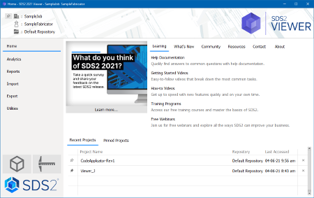
Change Job: Changes projects. You will be prompted to select the Fabricator and then Job.
Modeling: Launches the 3D model viewer.
Drawing Editor: Launches the 2D drawing viewer.
Export > Project Transfer: Unpacks projects from one SDS2 site to another and places the Job and Fabricator information in the correct location inside of the data directory. This only works with projects packed using Project Transfer .
Utilities > User and Site Options: Selects options that allow you to set up how SDS2 Viewer performs on an individual workstation.
Analytics: A snapshot of information about the currently loaded project. This information is only displayed when the "Refresh" button is clicked.
Reports: A list of reports that can be accessed to retrieve information from the 3D model or the 2D drawings.
Utilities > Member Review: Displays a list of members in the project that can be reviewed on an individual basis.
Export > 2D > Plotting: Prints 2D drawings.
Export > 2D > Export PDF Drawing: Export drawings directly to PDF files.
Modeling
Open View: When first entering Modeling , you are prompted to select a predefined Erection view. The view may be a plan view, elevation view or an isometric view. Once in the model, views can be changed by using the Open View icon (shown to the left), the File pull-down menu, or by using the right-click menu.
Pan, Rotate and Zoom: Pan by pressing and holding the middle mouse button, then moving the cursor to the desired location in the model. Rotate by holding down the Shift key, then press and hold the middle mouse button. While the middle button is pressed, move the cursor around the screen. Zoom in and out by scrolling the mouse wheel forward to zoom in, and backward to zoom out. The right-click and Navigate pull-down menus have options to perform these functions if the mouse does not have the referenced buttons.
Depth Check: Controls the dimensions that the you see into and out of the current view. The elevation is shown in the upper middle of the default toolbar, and the Depth Check is to the right of the elevation (shown below). If the elevation is at 10-0 and if Depth Check is on and set to In 3-0 and Out 3-0, you will see any items that are between the elevations of 7-0 and 13-0.

Display Options: Controls which items are shown in the model. These items include Piecemarks, Section sizes, Holes, Bolts, Welds, Cranes, Notes, and others. If the items are checked, they will be displayed in the model.
Point Locators: Used to locate points to add construction lines or for using the Ruler command. A few point locators are listed below.
Intersection of Construction Lines (INCL) — Locates a point where two construction lines intersect.
Exact Point — Locates a point at the end of a member.
Vertex Point — Locates a point at the corners of any material.
Free Point — Locates a point anywhere within the 3D model.
Construction Line Add: Adds a construction line to the model that you can use to pick points to measure between two locations. This command can be invoked on the toolbar or through the Model pull-down menu. The command needs two points to put a construction line between. There is not an end to a construction line; it will go through the entire model space.
Ruler: Displays the distance between two points selected using the Point Locators. If the window remains open and two additional points are selected, the Angle tab will display the angle between the two planes selected.
Solid vs. Stick: The model can be displayed in stick or solid form. The materials, bolts, holes and welds that make up a member can be seen when that member is displayed in a solid form. Also, members in a solid form may be color-coded according to their type. Members will be in stick form when entering Modeling . To turn members to solid form, you can select the member(s), right-click and select which solid form is wanted. You may also access the solids through the View pull-down menu.
Review: Brings up a window with information about entities within the model. Double clicking or right-click > Review are the best ways to bring up a Review window. Information about a specific member, material, bolt, hole, weld, and others can be accessed and reviewed.
Member Isolate: Displays only the member selected and shows all the views associated with it. This also allows you to have a clear view to take dimensions or review information on that member.
Design Calculations: Provides detailed information on system connections within the model. This information comes in report form, which includes loading information on the connection, formula results, and connection specifications.
Drawing Editor
Drawing Types: Upon starting the Drawing Editor , you are prompted to select a drawing. Member details, erection view drawings, submaterial details, detail sheets, erection sheets, and gather sheets are the main drawing types that can be viewed. With a drawing type selected, a list of corresponding drawings will be shown on the left-hand side of the screen. Double clicking or selecting and pressing " OK " will open the drawing for viewing.
Bill of Material: Shows detailed information about the member and material that is on the drawing or sheet. The detailer will have set up what information is shown in the Bill of Material. Information will generally include member piecemark, minor mark, description, weight, and length.
Review 2D Item: Accessed through the Tools pull-down menu, this command brings up a window with information on different entities within the drawing. Review can be done on material, bolts and holes.
page 1