SDS2 Home
- General Overview
- Navigating
- Search
- Opening Modeling
- Opening Drawing Editor
To open SDS2 Home: From the Start menu in Windows, choose SDS2 xxx, where xxx is the version number.

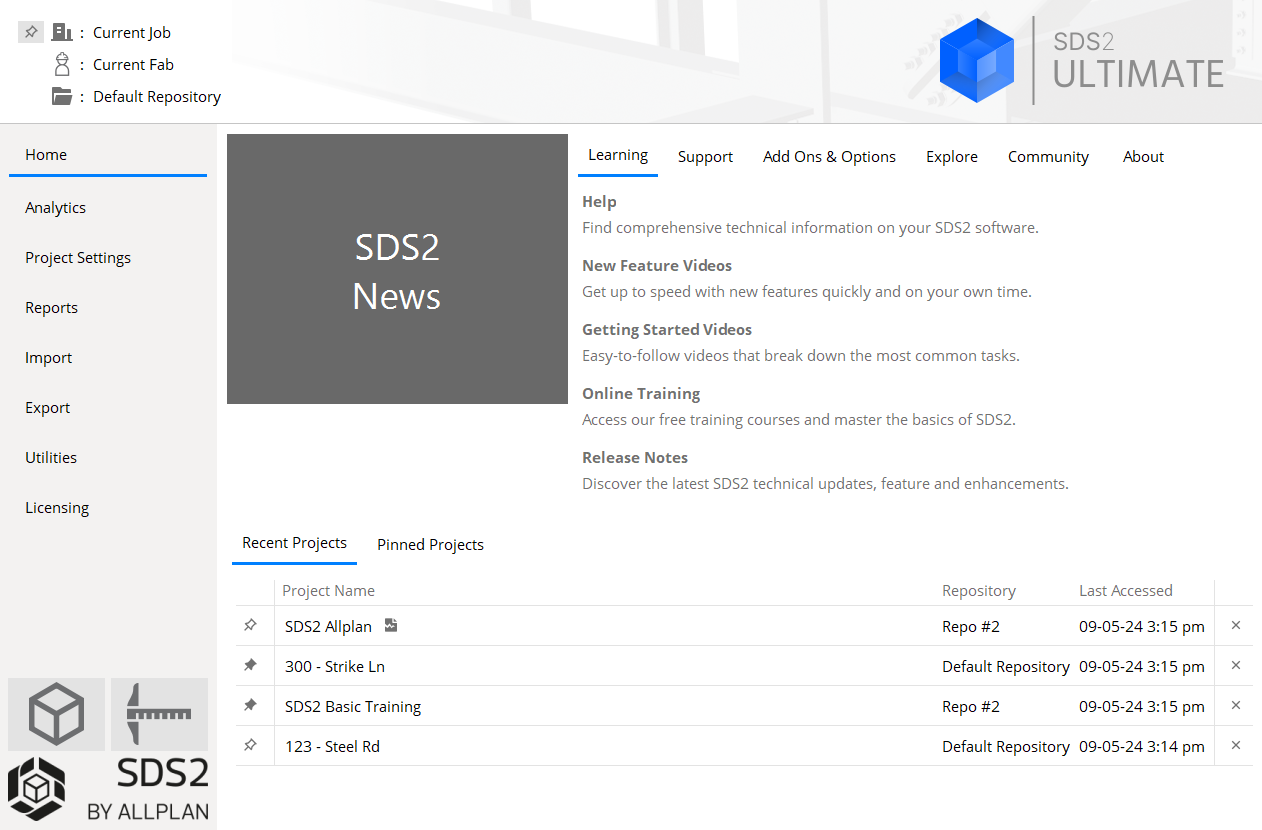
Reports the current Job, Fabricator, and repository. The jobname and fabname are buttons -- click one to change the current Job or Fabricator.
The Job button tells you the name of the current Job. Click the button to change your project, or create a new one. Alternatively, you can Activate a recent project to change the Job and the Fabricator.

Click to pin the current Job to the Pinned Projects tab.

Click to unpin the current Job
The Fabricator button tells you the name of the current Fabricator . Click it to change your Fabricator . Alternatively, you can Activate a recent project to change the Job and the Fabricator.
The Repository button tells you the name of the Job repository (file folder) where your current Job is stored.
About
Shows you the current version of SDS2, as well as the program name and its architecture.

click to copy SDS2 version information to the Windows clipboard. The SDS2 data directory:
An example of SDS2's data directory.
Depending on how SDS2 was installed, the data directory for your current version of SDS2 may or may not be shared by other SDS2 Editions and other SDS2 versions that use that same data directory.
Be aware that certain files that are distributed with SDS2 are overwritten in the following folders
in the SDS2 data directory, and consequently may change each time that you install a new version of SDS2 software:
SDS2 updates archival files in
aus_mtrl shape file from the
Recent Projects
The Recent Projects table lists the last five projects that you have made current by clicking either the Job or the Activate button, in the order in which you previously accessed them. Click a project's label to make it the current Job.
× Click the "x" next to a project's name to remove it from the table.
Click this pin to add this project to the Pinned Projects table.
Click this pin next to remove this project from the Pinned Projects table

indicates a project that can no longer be found by SDS2.
Pinned Projects
The Pinned Projects table lists the projects that you have pinned. Click a project's label to make it the current Job.
× Click the "x" next to a project's name to remove it from the table.
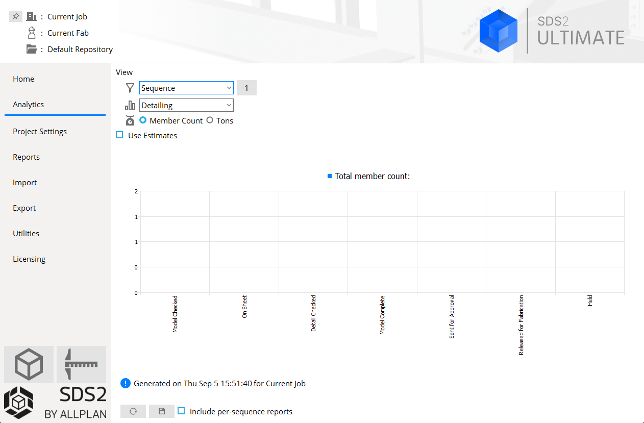
View
Choices made here select members and information for display in charts that you can save to a PDF file.
Chart filter: All Members or Sequence or Zone.
Example: Two sequences selected

This sets the number of members that will be included in the Member Count reported in the Detailing, Approval, Fabricator, Erector and BIM charts. If, as in the example above, two sequences are selected, then the Member Count and Tonnage will include all members except existing members that are in those two sequences. When 'All members' is selected, all members except existing members in your current 3D model are included in the Member Count.
Chart set: Detailing or Approval or Fabricator or Erector or BIM.
Detailing reports Count, Tons and % of the Chart filter members. Tons are reported as tons (2,000 lbs) or metric tons (1,000 kg), depending on the primary dimension Units that are set in Fabricator Settings > Detailing > Drawing Presentation > the Primary Dimensions tab. The percentage (%) that is reported for a category on this tab reflects the number (count) of members in that category that are in the Member Count.
The links at left point to where you can input the information that this tab tracks. No links are provided for Model Checked and Detail Checked since these are activated member custom properties, which are user-configurable and therefore not documented individually.
Approval reports Count, Tons and % of the Chart filter members. Tons are reported as tons (2,000 lbs) or metric tons (1,000 kg), depending on the primary dimension Units that are set in Fabricator Settings > Detailing > Drawing Presentation > Primary Dimensions. The percentage (%) that is reported for a category on this tab reflects the number (count) of members in that category that are in the Member Count.
Reviewed is the total of members set to Approved or Approved as Noted, or Revise and Resubmit or Rejected. No link is provided for Detail Checked since it is an activated member custom property which is user-configurable.
Fabricator reports Count, Tons and % of the Chart filter members. Tons are reported as tons (2,000 lbs) or metric tons (1,000 kg), depending on the primary dimension Units that are set in Fabricator Settings > Detailing > Drawing Presentation > the Primary Dimensions tab. The percentage (%) that is reported for a category on this tab reflects the number (count) of members in that category that are in the Member Count.
The links at left point to help on Member Status Review, which is one location where this information may be input. The Total Members reported depends on the selection made to Information Selection By.
Erector reports Count, Tons and % of the Chart filter members. Tons are reported as tons (2,000 lbs) or metric tons (1,000 kg), depending on the primary dimension Units that are set in Fabricator Settings > Detailing > Drawing Presentation > the Primary Dimensions tab. The percentage (%) that is reported for a category on this tab reflects the number (count) of members in that category that are in the Member Count.
The links at left point to help on the Member Status Review window, which is one of the windows where this information may be input. Available to Erect and Rejected Steel are based on activated member custom properties.
BIM reports Count, Tons and % of the Chart filter members. Tons are reported as tons (2,000 lbs) or metric tons (1,000 kg), depending on the primary dimension Units that are set in Fabricator Settings > Detailing > Drawing Presentation > the Primary Dimensions tab. The percentage (%) that is reported for a category on this tab reflects the number (count) of members in that category that are in the Member Count.
You can input the information that is tracked on the BIM chart to the Member Status Review window (which the links at left point to). You can also input this information in Update Attributes.
Chart type: Member Count or Tons.
Selecting Member Count causes the chart to report -- by status -- a count of members.
Selecting Tons causes the chart to report -- by status -- the tonnage of members.
Use Estimates  or
or  .
.
If Use Estimates
If Use Estimates
Analytics buttons and options:
Refresh updates the charts with the member count and tonnage of members in the 3D model, if these quantities have changed since you last opened Home .
Save as PDF saves the chart currently displayed on the Analytics tab and tabular data based on it to a PDF file.
Include per-sequence reports:
If include per-sequence reports
If include per-sequence reports
Include per-zone reports:
If include per-zone reports
If include per-zone reports
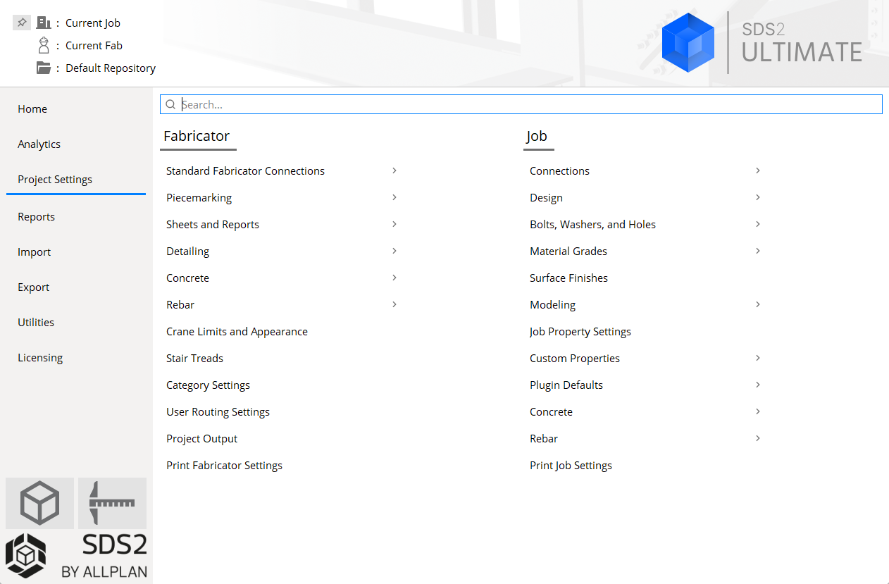
Project Settings Overview:
- To apply certain changes made in Job Settings and Fabricator Settings to the 3D model, you should mark for processing (or Process Selected) any members that you want changed, then Process and/or Create Solids. To apply to member/submaterial details changes that you have made to Fabricator Settings , you only need to automatically detail the affected members/submaterials.
- If the Current Fabricator and Master Fabricator are different Fabricators, the settings for End Plates Standard Piecemarks, Shear Plates Standard Piecemarks, and the Base/Cap Plate Schedule are disabled, preventing you from editing those settings screens. Your Current Fabricator must be the same Fabricator as the Master Fabricator in order for you to edit those settings screens.
Search box:

searches Job and Fabricator settings screens for terms that you enter into it. Click the "×" to clear the search term(s).
Also see:
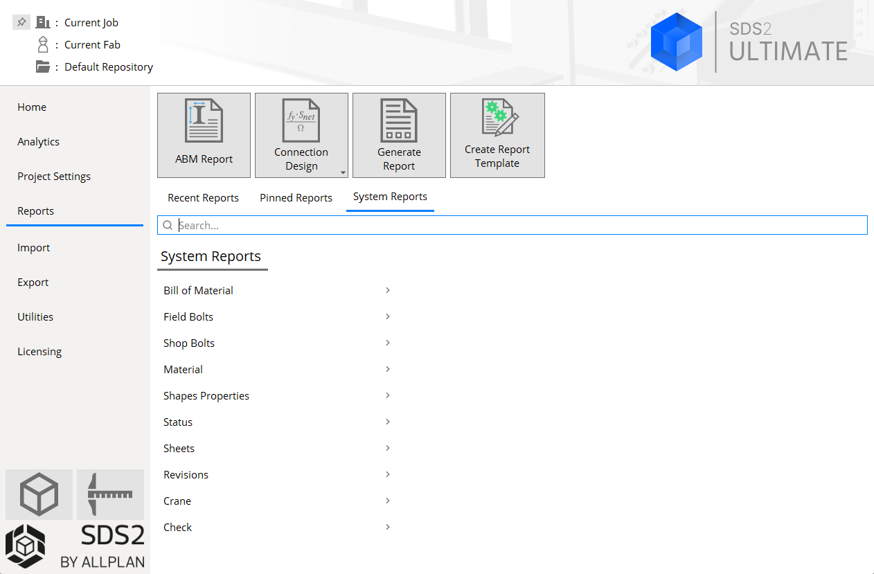
Reports > buttons

ABM Report opens the same ABM Report window as choosing Reports > Advanced Bill of Material will open in Modeling or the Drawing Editor . ABM reports are system reports and not Report Writer reports; however, Report Writer reports can mimic the functionality of system reports.

Connection Design Calculations opens a menu from which you can choose these reports:
- Expanded Calculations. This is the same report as choosing Reports > Expanded Calculations > Expanded Calculations in Modeling or the Drawing Editor.
- Design (short) Calculations. This is an abbreviated version of the Expanded Calculations report.
- Connection Cube Report. This generates a report of the Connection Cube(s) you select.
- Connection Group Report. This generates a report of the Connection Group(s) you select.
- Schedules of Minimum. This generates a report of the Schedule of Minimums for Structural Connections and the Schedule of Minimums for Single-Plate Shear Connections.
- Design Procedures and Notes. This generates a report of general information related to your job's Connection design method.

Generate Report can open any report created with Report Writer . Such reports can be found in the current version of this program's data directory in the reports folder. This folder contains subfolders:
- The Detailing folder contains Report Writer reports.
- The SDS2_User folder contains User reports. These are Report Writer reports that mimic the functionality of System reports. Deconstructing these reports is an excellent way to learn the SDS2 Report Writer . You can save modified versions of these reports side-by-side with the original reports, or you can modify the original reports.

Create Report Template opens the Report Writer with a blank, untitled report.
Search box
searches system report names for terms that you enter into it. Click the "×" to clear the search term(s).
Reports > System Reports
System Reports are the same reports that can be found on the Reports menu in Modeling and the Drawing Editor.
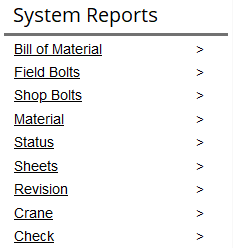
These are not Report Writer reports. By default, the Generate Report button accesses same-named reports which mimic the functionality of these reports and are Report Writer reports. Click items directly to navigate reports. To navigate backwards, click the System Reports breadcrumb
You will also leave behind a breadcrumb of the link that you clicked to open the report category:
Recent Reports
The Recent Projects table lists the last five reports that you have selected.
Pinned Reports
The Pinned Reports table lists reports that you have pinned.
Click this pin next to the current Job to add it to the Pinned Projects tab.
Click this pin next to the current Job to remove it from the Pinned Projects tab.

Indicates a system report.
× Click the x next to a project's name in the Pinned Projects tab to unpin it.
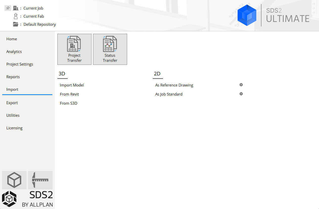
Import > buttons

Project Transfer packs or unpacks an SDS2 project.

Status Transfer lets you transfer key information about status or custom properties. 3D
Import Model opens the Import Model window, from which you can import nearly any type of Neutral file .
From Revit opens a Synchronize from Revit file selection dialog, from which you can import a Revit Structure XML file .
From S3D opens a Synchronize from S3D file selection dialog, from which you can load an S3D neutral file.
2D
As Reference Drawing opens a file selection dialog, from which you can select CAD files to be imported as reference drawings.

opens the Drawing Import Settings window. This window lets you set which pen numbers you want assigned to particular AutoCAD pen numbers when you import .dxf, dxb. or .dwg files . As Job Standard opens a file selection dialog, from which you can select CAD files to be imported as job standard details.
opens the Drawing Import Settings window.
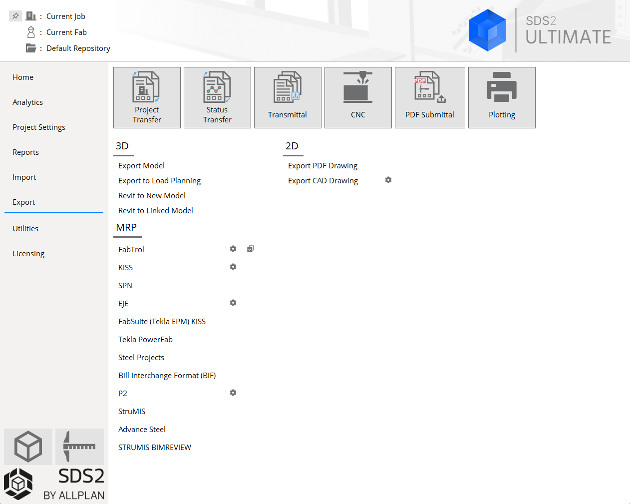
Project Transfer packs or unpacks an SDS2 project.
Status Transfer lets you transfer key information about status or custom properties.

Transmittal outputs a variety of file types: CNC files, CAD files, IFC models, lists, etc.
CNC: outputs CNC files for a particular CNC configuration type . Click here for information about the Computer Numerically Controlled window, which is the CNC module's main menu. Click here to access a contents page for all CNC help topics.
3D
Export Model lets you can choose among several file types to export the SD2 model to. The model export options are as follow:
- IFC2x3
- EM11 (IFC2x3)
- IFC4
- CIS2
- Steel detailing neutral file
- STEP
- IGES
- DXF/DWG
- VRML
- U3D
- PML code generator
- Bechtel WALKTHRU output
Export to Load Planning: exports an IFC2x3 model of the current SDS2 project. Using this tool will have the ideal settings used for Load Planning.
Revit to New Model opens a Synchronize to Revit file selection dialog, from which you can export your entire SDS2 model to a Revit Structure project in which no roundtripping has yet been done.
Revit to Linked Model opens a Synchronize to Revit file selection dialog, from which you can export a Revit Structure XML file. Choose this tool if you have previously done an Import Model from Revit and you now wish to export your changes back to Revit so that the two models can become synchronized.
2D
Export PDF Drawing outputs sheets as PDF files.
Export CAD Drawing can export any type of Drawing Editor drawing.
Plotting opens a selection dialog from which you can choose sheets for plotting and apply scaling and other printing options to them.
MRP
- Fabtrol
- KISS
- SPN
- EJE
- Fabsuite (Tekla EPM) Kiss
- Tekla PowerFab
- Steel Projects
- Bill Interchange Format (BIF)
- P2
- StruMIS
- Advance Steel
- STRUMIS BIMREVIEW
opens the settings window for the Export type .

does the same thing as Mark /Unmark for MRP export in Change Options .
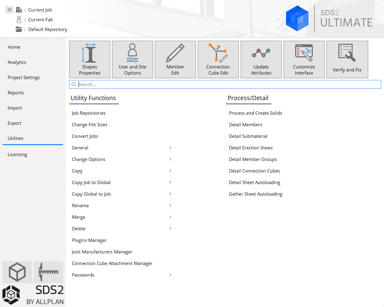

Shapes Properties opens dialog for selecting the Shape file to edit or review in Shapes Properties .

User and Site Options opens the User and Site Options window. Options on that window apply to you alone (user options) or to your entire site (site options). Edit:
Member Edit opens a member selection dialog. The appropriate Edit window is opened for the members that you chose.
Connection Cube Edit opens a connection cube selection dialog. The appropriate Edit window is opened for the connection cube that you chose.

Update Attributes directly updates the status of members without your having to open their edit windows.

Customize Interface opens a dialog from which you can select a role configuration file to customize. These configure keyboard shortcuts, ribbon layout, and context menus.

Verify and Fix can be used in the event that data becomes corrupted or files become locked. However, Verify and Fix should not be run if there are other people on your network who are using your current Job.
Search box:
searches utility functions screen for terms that you enter into it.
Licensing
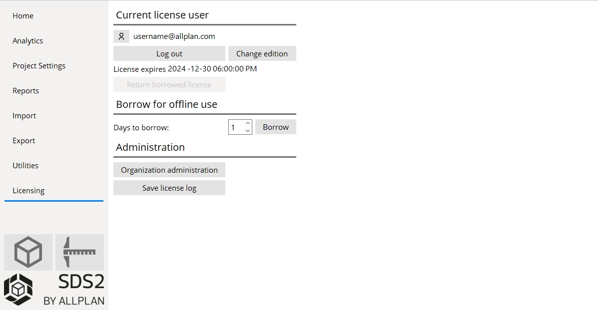
Current license user
The ![]() button: Opens a web browser so that
you can log into and view the default user's SDS2 account profile page. The default user name is displayed
next to the button.
button: Opens a web browser so that
you can log into and view the default user's SDS2 account profile page. The default user name is displayed
next to the button.
Log out: Allows you to clear the default user from the computer and re-login to licensing. To log out, you must first close all windows of SDS2.
If Home > Utilities > User & Site Options > General > Confirm on log out is checked, a Log out dialog will ask you to confirm your choice. Choosing Yes, don't ask again will not only log out the user, it will also uncheck Confirm on logout in User and Site Options.
Change Edition: Allows you to switch between Ultimate, Modeling, Drafting and Basic Editions based on your license. Selecting a different edition will close and relaunch SDS2 in the selected edition and remember this selection the next time SDS2 is opened.
Note: All other SDS2 screens must be closed and the user must not have a borrowed or contingency license.
License Expires: A read-only field that reports when the license on the server or a borrowed license expires.
Return borrowed license: Returns a borrowed license before it expires. If a license has not been borrowed this button is disabled (grayed out).
Borrow for offline use
Days to borrow: 1 to 28 days. This is the length of time that you can Borrow a license for offline use when you click the borrow button.
Borrow: Allows you to use a license from the license pool offline for a requested period of time (maximum of 28 days) for use on a single computer when the computer may not be connected to the internet for an extended period of time. Once you click Borrow, the License expires field will indicate the date the license will be returned, unless you click Return borrowed license earlier.
The borrowed license is returned to the license pool either when it expires or when you return it by pressing the Return borrowed license button. During this time, it will be reserved in the organization's license pool, even if SDS2 is not being used on that computer.
Note 1: Pressing Log out does not return a borrowed license from a computer. If you later sign back into that computer using the same SDS2 licensing account and the same Window user account, SDS2 will still use the borrowed license.
Note 2: Return borrowed license applies only to the borrowed license of the currently logged on Windows user. There is no way for you to return another user’s borrowed license unless you are using the borrower’s Windows user account that is logged on to the same computer on which the license was borrowed.
Administration
Organization administration: Opens a web page that allows a license administrator to log in to your organizations license administration page.
Save license log: Opens a Save log as dialog, allowing you name the file and to select the folder that you want to place a log file into. The log is a timestamped list of licensing events such as license check-ins, check-outs, etc
Click items directly to navigate project settings.
Example 1: Clicking Project Settings > Job > Design in the search results list removes the names of the Job and Fabricator links, and instead only displays the names of design settings screens: Design Settings , Plate Design Settings , Field Clearances , etc.
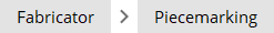
Example 2: Clicking Project Settings > Fabricator > Piecemarking link displays the names of piecemarking settings screens: All-Bolted Clip Angles,Bolted/Welded Clip Angles , All Welded Clip Angles , etc. Clicking All-Bolted Clip Angles opens that settings screen.
Breadcrumbs: If you click topics, they will leave a breadcrumb trail; for example:
Navigating backward: click any topic's breadcrumb to navigate to that screen again. In the example above, clicking Fabricator would display Fabricator links on the home screen.
Click the name of a search result to open its screen:
Example 1: Clicking Job > Design > Field Clearances opens the Field Clearances screen.
Example 2: Clicking Shear Tees under the Field Clearances search result opens the Field Clearances screen.
You can minimize categories:
Example: When searching project settings, your search may return both Job and Fabricator options:

Click the down arrow next to a category to minimize it:
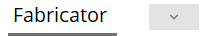
Hide Fabricator settings by clicking the down arrow. When a category is hidden, a control appears at the bottom of the search results list, like this:
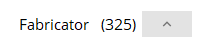
Open Fabricator settings by clicking the up arrow. The (number) indicates the search term entered matches that many Fabricator items, which are hidden from the list until you click the up arrow.
Breadcrumbs in search:
When navigating search results, if you click on a breadcrumb after clicking on a search result, you lose the search results. To preserve your search results, click Cancel on the settings screen that opens.
1. This procedure applies to an entirely new Job or to an already developed Job. At Home , click the Launch Modeling button.

2. One of the following happens.


Possibility 1: The Select One Erection View selection dialog opens if you have created erection views in your current Job and if you have not previously set an erection view to
Possibility 3: This possibility happens when you have previously designated a default erection view for your current Job. You can designate a default view by checking the box for
3. Modeling opens the perspective view . Modeling is where you construct , review and modify a 3D structural model.
1. Click the Launch Drawing Editor button.
Note: Drawing Editor sessions can also be started in Modeling by using Show Sheet, Show detail, Show Detail Other, or by pressing the Detail Member or View detail button on a member edit window. Multiple sessions can be open at the same time.
2 . A Drawing Editor window opens with the Drawling List Panel expanded. In the selection list, double-click a Detail drawing to open it or select a different Drawing Type.
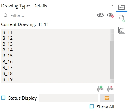
Alternative: Click the New Drawing button to create a new drawing.

