The Base / Cap Plate Schedule window ( Job Settings )
- This read-only window lets you review the settings for user base/cap plates that are available to users of a full-featured SDS2 program working on this same current Job. To specify a user base/cap plate on a column in full-featured SDS2 program, the user enters a number that corresponds to a line on this schedule.

To open this window, your current Fabricator needs to be the Master Fabricator . To " Change Fabricator " press the "fabname" found at top, left of Home .
Also see :
- User base/cap plates (type of plate defined here)
- Process and Create Solids (selections here applied during)
- Column Review window (where definition can be applied)
- Auto Std Connections window (other way a definition can be applied)
- User Defined Connections (other way a definition can be applied)
home > project settings > job > connections > | classic | top
To open Base / Cap Plate Schedule :
A special requirement: Your current Fabricator needs to be the Master Fabricator in order for you to use the following methods to open this window.
Method 1 : Home > Project Settings > Job .> Connections > Base / Cap Plate Schedule .
Method 2 : In Modeling or the Drawing Editor (classic), choose Settings > Job Settings > Base / Cap Plate Schedule (classic), or use a keyboard shortcut , or click the icon.
home > project settings > job > connections > | classic | top
Columns on Base / Cap Plate Schedule :
Piecemark: The standard submaterial mark (up to 61 characters)
A ' standard submaterial mark ' shown here will be assigned to all duplicates of this plate when columns on which this plate is applied undergo Process and Create Solids in a full-featured SDS2 program.
Plate type: Rectangular or Round .
' Rectangular '

|
' Round '

|
' Rectangular ' specifies a rectangular plate. If this option is selected, pressing the " More... " that the user a full-featured SDS2 program has defined an L-shaped or X-shaped or T-shaped plate based on the rectangular plate.
' Round ' specifies a round plate. Pressing the " More... " may reveal that users of a full-featured SDS2 program have specified a hole pattern for the round plate using options that are available under the " Round Plate Holes " tab.
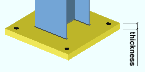
Thickness: The distance (in the primary dimension " Units " or in other units ) between the two faces of the plate that have the largest surface area.
Length or Diameter (parallel to web * ): The length (in the primary dimension " Units " or in other units ) of either edge of the base/cap plate that is parallel to the column web.
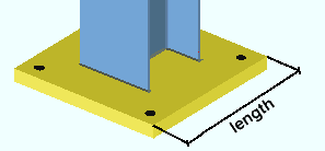
* For a column under or over a beam, or when a joist frames to a column with a user cap plate, the length of the base/cap plate automatically is rotated to be parallel with the workline of the beam or joist. It doesn't matter how the column is rotated, the length of the base/cap plate will be parallel with the work line of the beam or joist.
Width (parallel to the flange * ): The length (in the primary dimension " Units " or in other units ) of either edge of the base/cap plate that is parallel to the column flanges as shown in cross section.
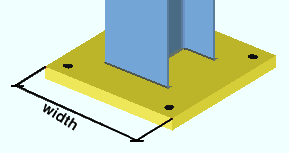
* For a column under or over a beam, or when a joist frames to a column with a user cap plate, the width of the base/cap plate is perpendicular to the workline of the beam or joist. It doesn't matter how the column is rotated, the " Length " of the base/cap plate will be parallel with the workline of the beam or joist.
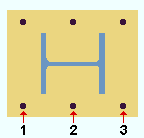
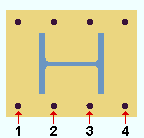
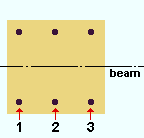
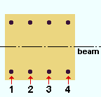
Hole columns: The quantity of hole columns. Hole columns run parallel with the column flanges ( or perpendicular to the beam/joist workline).
|
If " Plate rotation " is ' 0 ' for a user base/cap plate on a column with an indeterminate end , hole columns run parallel with the column flanges. |
|
If " Plate rotation " is ' 0 ' for a user base/cap plate on a column to a beam or joist, hole columns run perpendicular to the work line of the beam or joist. |
Note: When there are an odd number of columns of holes (1, 3, 5, 7, etc.), the middle column is centered with respect to the length of the base/cap plate.
Column spacing: The center-to-center distance (in the primary dimension " Units " or in other units ) between columns of holes. This distance is measured parallel with the column web ( or parallel with the beam/joist workline).
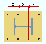
|
x = column spacing |
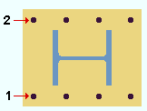
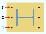
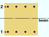
Hole rows: The quantity of hole rows. Hole rows run parallel with the column web ( or parallel with the beam/joist workline).
|
If " Plate rotation " is ' 0 ' for a user base/cap plate on a column with an indeterminate end , hole rows runs parallel with the column web. |
|
If " Plate rotation " is ' 0 ' for a user base/cap plate on a column to a beam or joist, hole rows run parallel with the work line of the beam or joist. |
Note: When there are an odd number of rows of holes ( 1 , 3 , 5 , 7 , etc.), the middle row is centered with respect to the width of the base/cap plate.
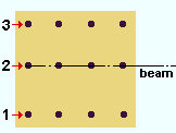
Row spacing: The center-to-center distance (in the primary dimension " Units " or in other units ) between rows of holes. This distance is measured parallel with the column flange ( or perpendicular to the beam/joist workline).
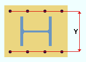
Y = row spacing
Bolt Diameter: The diameter (inches or mm) of the shank of the bolt to be inserted into the plate. This diameter, along with the " Hole type ," is used to calculate the default " Hole diameter " of holes in the plate.
Hole Type: Anchor bolt hole or Standard round or Oversized .
An ' Anchor bolt hole ' is a hole for anchor bolts in a column base plate. By default, it is 9/16 inch larger than an input bolt diameter of 3/4 (see AISC Thirteenth Edition Table 14-2, p14-21). Holes must be this type in order for them to be automatically dimensioned during auto detailing of erection views in a full-featured SDS2 program .
A ' Standard round ' hole is perfectly round and typically 1/16 inch larger than the input bolt diameter. See Table J3.3 or Table J3.3M ( AISC Thirteenth Edition , p16.1-105).
An ' Oversized ' hole is perfectly round and typically 3/16 inch larger than the input bolt diameter. See Table J3.3 or Table J3.3M ( AISC Thirteenth Edition , p16.1-105).
Steel Grade: Any grade of steel that is listed at Home > Project Settings > Job > Steel Grades for Plates & Bar Stock may be shown here. If ' Default (xxx) ' is selected, the Home > Project Settings > Job > Design > Design Settings > " Default steel grade for Base / Cap Plate Schedule " is applied.
Hole Diameter: 0 (zero) or a distance (in the appropriate " Units ") to designate the actual hole diameter.
' 0 ' (zero) designates a CNC mark. ' 0 ' does not stop holes from being created. An entry of ' 0 ' to " C/C length " and " C/C width " stops holes from being created.
![]() opens the Base / Cap Plate Weld Options window, which can be used to appy weld patterns, weld types and weld sizes for attaching the base or cap plate to a column.
opens the Base / Cap Plate Weld Options window, which can be used to appy weld patterns, weld types and weld sizes for attaching the base or cap plate to a column.
![]() opens the Advanced Base / Cap Plate Options window, so that you can review definitions for X-shaped, T-shaped and L-shaped plates or for " Round Plate Holes ."
opens the Advanced Base / Cap Plate Options window, so that you can review definitions for X-shaped, T-shaped and L-shaped plates or for " Round Plate Holes ."
home > project settings > job > connections > | classic | top
