"  NS/FS Clip Conn1 " & "
  NS/FS ClipConn2 " connection design locks (4 leaves)
| Horizontal brace gusset clip angles can be designed for a horizontal brace (any material type) to a beam-beam corner in order to field bolt the gusset plate to each beam's web. " |
|
|||
|
"
|
" (" Gusset to clip connection " = ' Welded ')  |
||
|
|
||
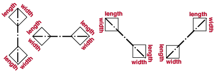
Length & width of the gusset plate:
Width = "
NS/FS Clip Conn1 "
Length = "NS/FS Clip Conn2 "

user defined | horizontal brace edit | top
Connection design locks :
| Locks not called out or dimensioned on the drawing are marked ( not depicted ). |
![]() NS Clip Conn1 /
NS Clip Conn1 / ![]() FS Clip Conn2
FS Clip Conn2
(horizontal brace to a beam-beam corner, clip angles to the webs of the beams)
|
Clip angle(s) can be on ' Both sides ' or ' Near side ' or ' Far side ' of the gusset plate. You get a leaf for " |
:
Section size ( not depicted ):
Long leg to ( not depicted ):
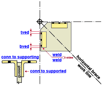
Connection to supported (gusset clip angle, NS or FS, leg welded or bolted to the gusset plate) :
When "
Connection specifications " > " Gusset to clip connection " is set to ' Welded ', you get a " Weld size " entry field, but no options for bolting:
Weld size ( weld ):
When the " Gusset to clip connection " is set to ' Bolted ', you get the following " Connection to supported " options for shop bolting the brace to the gusset plate. " Connection to supported " settings can be different than the entries made to " Connection to supporting " fields.
Bolt diameter ( not depicted ):
diameter of leg-to-gusset shop bolts 
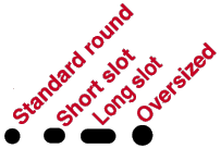
Hole type ( not depicted ):
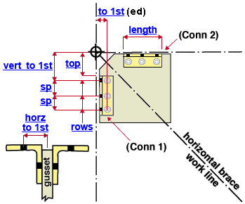
Rows ( not depicted ):
Vertical to 1st hole ( not depicted ):
Vertical hole spacing ( not depicted ):
Top vertical edge distance ( not depicted ):
Bottom vertical edge distance ( not depicted ):
Connection to supporting (beam corner gusset clip angle, NS or FS, leg that field bolts to one supporting beam) :
Regardless of whether the " Gusset to clip connection " is set to ' Welded ' or ' Bolted ', the connection to supporting is a field bolted connection with following options:
Bolt diameter ( not depicted ):
diameter of OSL field bolts 

Vertical to 1st hole ( to 1st ):
Vertical hole spacing ( sp ): A single vertical spacing distance or variable hole spacing can be entered here.
VIDEO 
Variable hole spacing can be typed to locked " Vertical hole spacing " fields found in leaves named " Shear Tab "; "
Bent Plate " "
End Plate " and "
NS/FS Clip Conn 2 " (Recorded in SDS2 Detailing , v2016.)
Rows Spacing Result 5 3,5,3,3 4 spaces at 3", 5", 3" and 3" 5 3,5,2@3 4 spaces at 3", 5", 3" and 3" 5 3,5,3 4 spaces at 3", 5", 3" and 3"
(the last spacing -- 3 -- is repeated to fill the spaces that are required for the number of rows)5 3,5,3,3,2,3 End connection failure message (see below). End connection failure message: Variable row spacing specifies too many rows
Top vertical edge distance ( tved ):
