The Erection View Member Labels window ( Fabricator Settings )
| Settings on this window are read-only. They tell you how this window has been set up for this Fabricator in a full-featured SDS2 program . |
To open the Erection View Member Labels window :
Method 1 : Home > Project Settings > Fabricator > Detailing > Erection View Member Labels .
Methods 2, 3 & 4 : In Modeling or the Drawing Editor , choose Settings > Fabricator Settings > Erection View Member Labels (classic), or use a keyboard shortcut, or click the icon.
|
||

|
How to reproduce the example shown above:
At Project-creation time: The " Flavor " that was selected to create the custom properties used in the example was a modular flavor. You could use a legacy flavor to get the same results that are shown above, but the intermediary steps in these instructions assume that you selected a modular flavor.
Creating the properties: " UserComment1 " is the " Name " of a schema entry that was created by pressing the " Add " button on the Edit Schema window. The " Type " of the schema entry is ' String '. The " Prompt " is ' User comment 1 ." "
Add to Erection View Member Labels " was checked. Note : Checking the box for "
Add to Erection View Member Labels " is not required for creating a member label since a user can simply type the " Property name " instead of selecting it as described in the next paragraph.
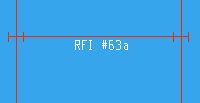
On this window: ' UserComment1 ' was selected as a " Property name " and specified to be output at the center of member line, below the member line. This setup is illustrated in the screen shot shown above, where the label RFI #63a appears at the center and below the member line.
After closing this window, the MEMBER Edit Properties window was opened (in Modeling ), and the entry ' RFI #63a ' was made to " User Comment 1 " under the "
User Namespace " leaf. Note : The MEMBER Edit Properties window is opened by pressing the " Properties " button that is found on a member window. As you can see in the screen capture shown above, the member was a beam in a plan view.
In Display Options , the box was checked for "
Custom properties ." When " OK " was pressed to close that window, the property labels were displayed in the model as shown in the screen capture above.
page 1 | contents | home > project settings > fabricator > detailing > | classic | top
