Channel material (topic)
Shape file specifications:

|
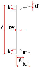
d = depth
tw = web thickness k = k distance tf = flange thickness bf = flange width g = flange gage |
Other shape file specifications: " Nominal Depth ," " Weight per Unit " (lbs/ft or kg/m), " Structural Properties ," " k distance (design) ," " Flange Bevel ."
Additional settings to the specifications found in the local shape file are defined on the Rolled Section Material window. These additional settings are read-only in Site Planning.
General description: Channel material is rolled steel with a cross section that is "C" shaped. It has two parallel legs, its top and bottom flanges, which are joined flush with a thinner web. The flanges of a channel are thickest at the web.Reference is often made to a channel being toed in, or toed out, depending on whether the flanges (or "toes") point toward you or away from you.Channel material is sometimes referred to as a "C section" or as "C material." Channels are used for beams, stair stringers, roof frames, bracing, facia and parapet framing.
Section size naming convention: C+nominal_depth+x+nominal_weight/length (pounds/foot U.S.). For example, C10x30 . Channel sections can be added (in a full-featured SDS2 program , not in Site Planning) using a entirely different naming convention. For example, MC sections can be entered as channels.
In Modeling and the Drawing Editor : A channel section must exist in the local shape file before the user of a full-featured SDS2 program can enter it as a " Section size " on a member and material edit window in Modeling , or before its weight will be automatically calculated when the user adds it to the " Description " field in the bill editor.
Submaterial piece marking: The default material mark prefix for channel material is c .
Steel grades are available for channel material are set up are set up using the Job Options list of " Channel Grades ."
page 1 | contents | material types | shapes properties | top