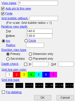
The Edit Erection View window :
The Edit Erection View window opens when you double-click an erection view with the selection filter set to ' All ' or to ' Grid Lines '. The " Pen color " and " Line type " affect Modeling only if the grid line is a straight . For a curved grid line , the " Pen color " and " Line type " will be applied to curved grid lines shown on 2D erection view crane placement drawings. View name: read-only . You cannot change the name of a view by editing it.
Auto pin to this view: N/A (not appicable) to SDS2 review stations. Click here for information about how this option works in a full-featured SDS2 program.
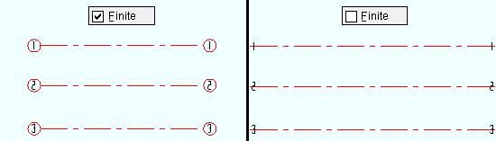
Finite:
or
. This applies when the grid line is straight.
If this box is checked ( Grid bubble setback: A positive number that is the factor by which the grid line will be extended in proportion to the diameter of its grid bubble. This applies when the grid line is " Finite ."
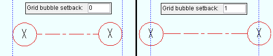
Entering ' 1 ' extends the grid line one grid bubble diameter -- half a grid bubble diameter at each end. Relative view depth: This option is available for grid lines that are elevation views . It sets the range of elevations within which a plan view 's reference elevation must be in order for this grid line to be visible. The " Top " elevation is the plan view elevation above which the grid line will no longer be visible. The " Bottom " elevation is the plan view elevation below which the grid line will no longer be visible.
axes :

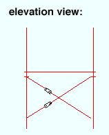
If you Open ( Ctrl + o ) a finite grid line that is shown in plan view, you will find yourself looking at an elevation view . Only members that are within the " Top " and " Bottom " elevations that are the specified " Relative view depth " will be shown in that elevation view.
Example 1: " Top " = ' 140-0 ' | " Bottom " = ' 130-0 '. The grid line is visible in a plan view whose reference elevation is ' 130-0 '. However, if you were to use View > Plan View to display a plan view at ' 141-0 ' or at ' 129-0 ', the grid line would no longer be visible.
Example 2: " Top " = ' 140-0 ' | " Bottom " = ' 140-0 '. The grid line would only be visible in a plan view whose reference elevation is ' 140-0 '. It would not be visible at any other elevation.
Note: Grid line visibility within a plan view is independent of the plan view's " Depth check " settings. It depends only on whether the plan view's reference elevation is within the grid line's specified " Top " and " Bottom " elevations.
Also see: View > Reference Elevation can be used to discover the elevation of your current plan view. The " Elevation " decoration, which you can place on your toolbar, displays a plan view's current elevation. Tools for changing a plan view's reference elevation are View > Plan View and View > Reference Elevation .
Arc or
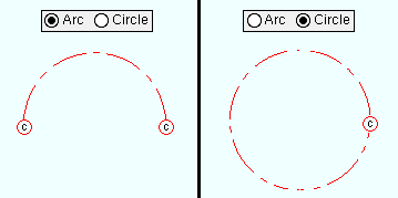
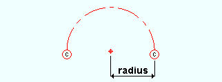
If ' Radius: The distance (in the primary dimension " Units " or other units ) from any point on the curved grid line to the curved grid's center.
Erection view type ( straight grid lines ): Primary or Secondary or Dimension only or Placement only . This applies to straight grid lines. The selection you make here sets how the grid line is to be dimensioned when an erection view wherein the grid line is visible is detailed in a full-featured SDS2 program . Locate options in Modeling such as INCL or INCM snap to points on straight grid lines of any of these types.
Tip: You can, in Display Options , turn on or off the display of grid lines ( curved or straight ) based on their type (' Primary ' or ' Secondary ', etc.).
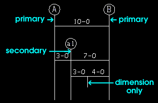
For straight grid lines , ' Primary ' dimensions appear above ' Secondary ' dimensions. ' Dimension only ' erection views are auto dimensioned, but not with grid markers. ' Placement only ' grid lines cannot be auto dimensioned. Erection view type ( curved grid lines ): Primary or Secondary or Dimension only or Placement only . This applies to curved grid lines . The selection you make here sets how the grid line is to be drawn when an erection view wherein the curved grid line is visible is detailed in a full-featured SDS2 program . In Modeling , Locate options snap to points on curved grid lines of any of these types.
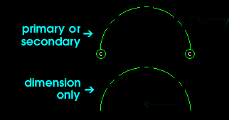
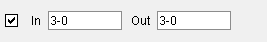
For curved grid lines , ' Primary ' or ' Secondary ' causes auto detailing to draw the bubbles at the ends of the grid line. ' Dimension only ' makes the bubbles not drawn. ' Placement only ' curved grid lines do not appear on erection view drawings. Depth check: " In " is the distance perpendicular to the plane of a view ( Modeling ). " Out " is in the direction opposite to the arrowhead. Defaults: User and Site Options > Modeling > " Depth check for new views ."

depth check controls
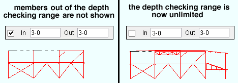
When this box is checked (
When the box is not checked (
Pen color: The color of the grid line associated with the erection view that you are adding or editing. For a straight grid line , this sets the color of the grid line in Modeling only. For a curved grid line , this also sets the Drawing Editor pen color that will be applied when an erection view wherein the curved grid line is visible is detailed in a full-featured SDS2 program .

Grid line type: The line type of the grid line that you are adding or editing. For a straight grid line , this sets the line type of the grid line in Modeling only. For a curved grid line , this also sets the Drawing Editor line type.

The button that is pressed sets the line type (dash pattern) of the erection view that you are adding. For detailing:
When this box is checked (
When the box is not checked (
Alternative 1 : Press " OK " (or the Enter key) to save the view.
Alternative 2 : Press " Cancel " (or the Esc key or the
button) to close this window without saving the view.
page 1 | contents | file > views/grids > add grid line | top