The Bent Plate Settings setup window ( Fabricator Settings ) (read-only)
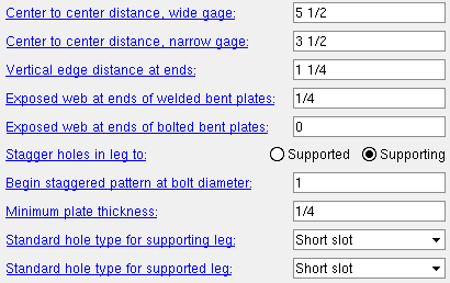
Settings that you can review on this window work in coordination with individual bent plate " Connection specifications " to set how the connection will be designed in a full-featured SDS2 program when the Beam Review > "
Connection type " > " Input connection type " is ' Bent plate ' or ' Auto standard ' or ' User defined '.
Also see :
- Bent plate input specs (for applying bent plate connections)
- Bent plates setup (bent plate connection setup options)
home > project settings > fabricator > standard fabricator connections > | classic
Method 1 : Home > Project Settings > Fabricator > Standard Fabricator Connections > Bent Plate Settings .
home > project settings > fabricator > standard fabricator connections > | classic | top
Center to center distance, wide gage: The center-to-center distance (in the primary dimension " Units " or in other units ) from the column of holes on the one bent plate to the column of holes on the other bent plate.
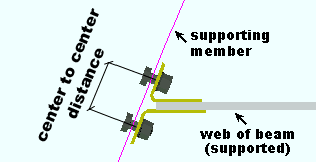
Effect on a full-featured SDS2 program: The double bent plate connection gage shown here applies in a full-featured SDS2 program to the design of wide gage, double bent plate connections. " Wide Gage " is a setting that can be selected when defining a bent plate in a full-featured SDS2 program
Center to center distance, narrow gage: The center-to-center distance (in the primary dimension " Units " or in other units ) from the column of holes on the one bent plate to the column of holes on the other bent plate.

Effect on a full-featured SDS2 program: The double bent plate connection gage shown here applies in a full-featured SDS2 program to the design of narrow gage, double bent plate connections. " Narrow Gage " is a setting that can be selected when defining a bent plate in a full-featured SDS2 program.
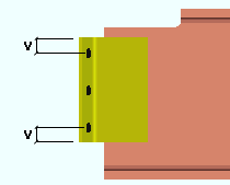
Vertical edge distance at ends: The vertical distance (in the primary dimension " Units " or in other units ) from the top (or bottom) edge of the bent plate to the center of the nearest hole.
|
v = vertical edge distance. This distance is measured perpendicular to the slope of the beam when the beam is sloping. |
Effect on a full-featured SDS2 program: The vertical edge distance shown here applies when connections are designed in a full-featured SDS2 program . Per AISC specifications, the vertical edge distance at ends of bent plates is preset to a minimum of 1 1/4 inch.
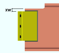
Exposed web at ends of welded bent plates: The vertical distance (in the primary dimension " Units " or in other units ) from the top (or bottom) edge of the bent plate to the cope on the supported beam.
|
xw = exposed web above a welded bent plate. A bent plate is welded when " Welded " is specified on the Beam Review window or for an auto standard or user defined connection. |
Effect on a full-featured SDS2 program: The exposed web distance shown here applies when connections are designed in a full-featured SDS2 program . If weld is required across the top of a bent plate, the exposed web must be sufficient to allow this weld.
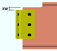
Exposed web at ends of bolted bent plates: The vertical distance (in the primary dimension " Units " or in other units ) from the top (or bottom) edge of the bent plate to the cope on the supported beam.
|
xw = exposed web above a bolted bent plate. A bent plate is bolted when " Bolted " is specified on the Beam Review window or for an auto standard or user defined connection. |
Effect on A full-featured SDS2 program: The exposed web distance shown here applies when connections are designed in a full-featured SDS2 program . Since no weld is required across the top of a bolted bent plate, the exposed web can be set to 0 (zero) inches if desired.
Stagger holes in leg to: Supported or Supporting . This field applies when bent plates are designed with bolt diameters as large or larger than those specified below .
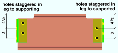
If ' Supported ' is selected, the full-featured SDS2 program will stagger the holes on the leg of the bent plate that attaches to the beam on whose review window the bent plate connection is applied.
If ' Supporting ' is selected, then the program will stagger the holes in the leg of a bent plate that is attached to the supporting beam (for a beam-to beam bent plate) or column (for a beam-to-column bent plate).
Begin staggered pattern at bolt diameter: The minimum bolt diameter (in the primary dimension " Units " or in other units ) at which bolt patterns should be staggered.
Effect on a full-featured SDS2 program: The bolt diameter shown here applies to the design of bent plates in a full-featured SDS2 program . The program will stagger the bolts on the bent plate if the connection requires a bolt diameter that matches or exceeds the diameter shown here.
Minimum plate thickness: The minimum thickness (in the primary dimension " Units " or in other units ) of bent plates.
Effect on a full-featured SDS2 program: The minimum thickness shown here applies to the design of bent plates in a full-featured SDS2 program . The program will only design bent plates that are as thick or thicker than this thickness. The actual designed thickness depends on the shear load that the bent plate is subjected to.
Standard hole type for supporting leg: Standard round or Short slot or Long slot or Oversized round or User slot #1 or User slot #2 .
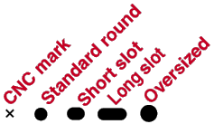
Effect on a full-featured SDS2 program: The hole type shown here applies to the bent plate leg that bolts to the supporting member. The program designs holes to " Connection design method " specifications, determining the specific size of a hole based on the diameter of the bolt that will eventually be fastened through that hole. For example, if you are using imperial dimensioning units and an AISC connection design method, a standard round hole is typically 1/16" larger than the bolt diameter, and an oversized round hole is typically 1/8" larger than the bolt diameter.
Standard hole type for supported leg: Standard round or Short slot or Long slot or Oversized round or User slot #1 or User slot #2 .

Effect on a full-featured SDS2 program: The hole type shown here applies to the bent plate leg that bolts to the supported beam. The program designs holes to " Connection design method " specifications, determining the specific size and shape of a hole according to the hole type and the diameter of the bolt that will eventually be fastened through that hole.
home > project settings > fabricator > standard fabricator connections > | classic | top