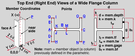
Top end (right end) of a wide flange column:
Click a point label ( A or B or etc.) to get an expression defining that point.

| point | position on top end | mem.right.location + mem.trans_to_global ( X , Y , Z ) | ||
| X | Y | Z | ||
| A | face A center line | 0 | mem.depth*.5 | 0 |
| B | center line, half depth | 0 | 0 | 0 |
| C | face C, center line | 0 | - mem.depth*.5 | 0 |
| D | face A, near side gage line | 0 | mem.depth*.5 | mem.gage *.5 |
| E | face A, far side gage line | 0 | mem.depth*.5 | - mem.gage *.5 |
| F | near side flange corner on face A | 0 | mem.depth*.5 | mem.bf *.5 |
| G | far side flange corner on face A | 0 | mem.depth*.5 | - mem.bf *.5 |
| H | near side flange corner inside face A | 0 | mem.depth*.5 -mem.tf | mem.bf *.5 |
| I | far side flange corner inside face A | 0 | mem.depth*.5 -mem.tf | - mem.bf *.5 |
| J | web near side toe of fillet | 0 | mem.depth*.5 -mem.k | mem.tw *.5 |
| K | web far side toe of fillet | 0 | mem.depth*.5 -mem.k | - mem.tw *.5 |
| L | web near side, half depth | 0 | 0 | mem.tw *.5 |
| M | web far side, half depth | 0 | 0 | - mem.tw *.5 |
| N | near side flange corner inside face C | 0 | - mem.depth*.5 +mem.tf | mem.bf *.5 |
| O | far side flange corner inside face C | 0 | - mem.depth*.5 +mem.tf | - mem.bf *.5 |
| P | near side flange corner on face C | 0 | - mem.depth *.5 | mem.bf *.5 |
| Q | far side flange corner on face C | 0 | - mem.depth *.5 | - mem.bf *.5 |
Columns on the above table :
point - the points ( A , B , etc.) in the above parametric point map are a few examples of reference points.
position on top end - entries to this column on the table describe (in words) the position where a particular point (A or B or etc.) is placed on the right end surface of a wide flange column. On a column, the right end and the top end are one in the same.
mem.right.location + mem.trans_to_global(X,Y,Z) - an expression similar to this one is automatically entered to the " Point 1 " and " Point 2 " fields of the parameric material window that appears when you Add Material operation. The expression "mem.right.location" is the right end work point of the member. The operation "+mem.trans_to_global(X,Y,Z)" defines individual X, Y and Z member coordinate distances and adds those distances to the member's right end work point in order to define a new point in global coordinates .
X is the X member coordinate distance from the right end member work point (mem.right.location) where the new point generated by the parametric will be placed. As illustrated above , a positive X distance is away from the left end (bottom end) work point of the column, whereas a negative X distance is toward the bottom end of the column. Note: The point location map illustrated above assumes that the column does not have a cap plate on it. Therefore, the column work point and the top of the column have the same X member coordinate. For a column that has a cap plate, the right end work point of the column is at the elevation of the top surface of the cap plate, while the top of the column material is at the elevation of the bottom surface of the cap plate.
Y is the Y member coordinate distance from the right end member work point (mem.right.location) where the new point generated by the parametric will be placed. As illustrated above , a positive Y distance is measured from the column workline toward face A, whereas a negative Y distance is toward face C.
Z is the Z member coordinate distance from the right end member work point (mem.right.location) where the new point generated by the parametric will be placed. As illustrated above , a positive Z distance is measured from the column workline toward the near side , whereas a negative Z distance is measured away from the near side.


