Left end & near side, beams, columns, braces, joists, legacy misc (topic)
Also see :
- Global coordinates (determine left end of a member)
- Member coordinates (0, 0, 0 point of member is on left end)
- Origin reference point (identifies member 0, 0, 0 point)
- Left end of a Concrete member (topic)
page 1 | contents | topics | top
The near side of members :
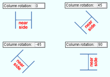
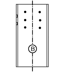
- The near side of a beam, column or brace is the side that is shown in the main view of that member's detail. Here's how to determine near side in the Modeling .
page 1 | contents | topics | top
Determining a member's near side by knowing its left end :
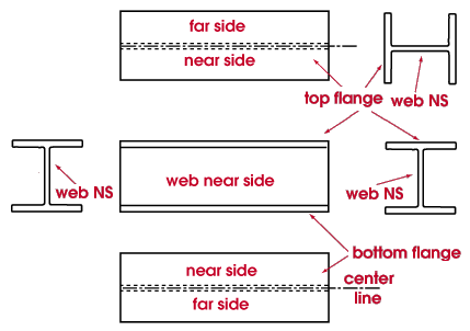
- The near side of a beam, column, or brace is the side that is shown in the main view of that member's detail. Knowing a member's left end can help you determine its near side in the model. When you are looking at web near side of a non-vertical member, its left end is to your left and its right end is to your right. The left end of a member that is detailed horizontal is also the end that appears on the left in its detail.
page 1 | contents | topics | top
Using piecemarks to determine a member's left end :
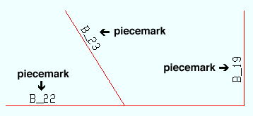
- The piecemark label of a member not shown as a cross section in Modeling is on the left end of the member. Exception: if the member is relatively short or you " Swap member ends ," this does not hold true.
page 1 | contents | topics | top
A member's origin reference point is on its left end :
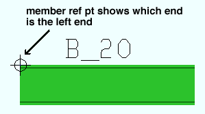
page 1 | contents | topics | top
Left end/ near side in member isolation :

- In member isolation , a member's MAIN VIEW is the same as that member's main view on its member detail, with its left end on the left (bottom in the case of a column), and its near side facing toward you.
page 1 | contents | topics | top
Using Status Display to show the left end and/or right end of members :
- In Status Display , you can select ' Member ' or ' Ends ' or ' Left ' or ' Right ' as the item to be color coded .
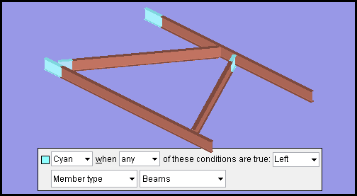
This example of a status display condition color codes beam left ends in the color cyan . If ' Right ' had been selected as the item to be color coded , the beams' right ends -- instead of their left ends -- would be cyan.
page 1 | contents | topics | top
Relating a member's left end to global coordinates :
Key concept: The left end of a beam, column, brace, legacy miscellaneous or etc. is the end that is closest to the global axis 0, 0, 0 point .
As members are added to the 3D model, each work point of the member is assigned a global coordinate position. Based on that global coordinate position, the program determines which end is the left end of a member as follows:
page 1 | contents | topics | top
Left end of a member in a plan view :
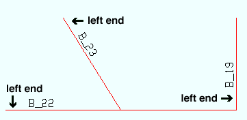
Left end of members in an elevation view :
In an elevation view , determining which end of a member is its left end can be a bit more tricky. This is because views have directions.
|
|
Before : This example shows a section view being cut across the top flange of a beam in a plan view. |
|
|
After : The resulting section view shows the left end of the beam on your left. |
|
|
Before : Here's a section view being cut from right to left across the top flange of a beam in a plan view. |
|
|
After : The resulting section view shows the left end of the beam on your right. |
Tip: In a plan view, face section view bottom up or right in. This will help you to more easily determine which end of a member is its left end. Click here for some examples.
An axes box is a tool that you can use to help you determine which end of a member is its left end in an elevation view.
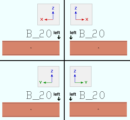
page 1 | contents | topics | top
End [0] versus end [1] :
End [0] is the left end of a member. End [1 ] is the right end of a member. Member ends are referred to in this way at the following locations:
| Reference | Location |
| end [0] or end [1] | Lock Ends Framing to Model Complete Member |
| [0] or [1] | Shear Thru Plate On [mem num] [end]
and Change base/cap plate weld pattern |
| Ends[0] or Ends[1] |
model module (parametrics) and
|
For a column, end [0] is the bottom end, end [1] is the top end.

