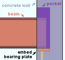
Bearing ' connection (beam to concrete)
|
||

|
Input connection type: ' Bearing ' or ' Auto standard ' or ' User defined '. | |
| Options: An " Embed schedule entry " selects an embed plate from the Embed Schedule . The " Pocket grout thickness " for this example was set to ' 0 ' (zero). | ||
| Comments: The embed plate is a custom member . A ' Bearing ' connection is not a system connection . A bearing embed can be an angle, channel or plate. | ||

|
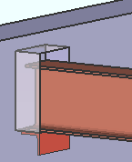
An embedded bearing angle. As is the case in the above example, the " Input connection type " is ' Bearing '. An angle was selected as the " Embed schedule entry ." By default, SDS2 connection routines automatically match the length of the angle to the width of the pocket that is created in the concrete wall. |

|
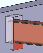
An embedded bearing channel. The " Embed schedule entry " is a channel. The length of the channel matches the width of the pocket. The " Side " erection clearance in the " |
More about the ' Bearing ' beam-to-concrete connection :
• An " Embed schedule entry " is not required to get "
Beam End Pocket " locks.
• The beam must frame to a concrete wall or tilt-up panel. A concrete license is required to get a connection to a tilt-up panel.
• When ' Bearing ' as the " Input connection type " for a beam end that does not frame to a concrete wall or panel, " Embed schedule entry " is disabled ( grayed out ) and you probably also get the connection failure message " No supporting member ."
• When ' Bearing ' is the " Connection type " on the User Defined Connections setup window, "
Frames to concrete wall " must also be checked on that same window.
• At Home > Project Settings > Job > Auto Standard Connections , beam bearing connections can be specified when the general framing condition is ' Beam to concrete '.
• Home > Project Settings > Job > Field Clearances > " Steel to concrete connections " options relate to the sizing of the beam end pocket and the positioning of the embed.