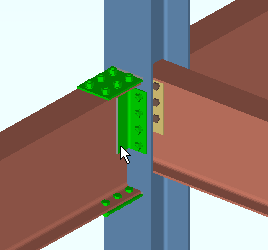
System Connections ( designed connections)
- Auto standard connections (beams, columns, joists)
- User Defined Connection (connection settings stored in a file)
- Clip Angle Connection (may be a moment connections)
- Bent Plate Connection
- End Plate Connection (may be a moment connection)
- Shear Connection (may be a moment connection)
- Seated Beam Connection
- Splice Plate Connection (beam to beam - may be a moment connection)
- Splice Plate Connection (column to column)
- Auto Base/Cap Plate
- Joist Connections (cannot be auto standard)
- VBrc Plate (cannot be auto standard)
- HBrc Plate (cannot be auto standard)
- Moment Connection (cannot be auto standard)
- Welded connection (cannot be auto standard)
- Fully welded moment
System connections are designed per the selected " Connection design method ."
Method Setup Window Design Specifications ' ASD14 ' ASD 14th Omega Factors AISC Steel Construction Manual,
Fourteenth Edition' ASD13 ' Omega Factors AISC Steel Construction Manual,
Thirteenth Edition' ASD 9 ' - - - AISC Manual of Steel Construction, Allowable Stress Design, 9th Edition ' LRFD 14 ' LRFD 14th Phi Factors AISC Steel Construction Manual,
Fourteenth Edition' LRFD 13 ' LRFD 13th Phi Factors AISC Steel Construction Manual,
Thirteenth Edition' LRFD 3 ' LRFD 3rd Phi Factors Manual of Steel Construction, Load and Resistance Factor Design, 3rd Edition ' CSA 10 ' CSA10 Phi Factors CISC Handbook of Steel Construction,
Tenth Edition' CSA 9 ' CSA Phi Factors CISC Handbook of Steel Construction,
Ninth Edition' CSA 8 ' CSA Phi Factors CISC Handbook of Steel Construction,
Eighth EditionSystem connections are designed based on the applied loads .
Beam Loads --------------------------------------------------------------------
--
Shear load Tension load Story shear Compression load Moment load
Column Loads ------------------------------------------------------------------
--
Load Splice uplift Moment Horizontal shear
Horizontal Brace Loads -----------------------------------------------------
--
Tension load Compression load
Vertical Brace Loads ---------------------------------------------------------
--
Tension load Compression load
Joist Loads -------------------------------------------------------------------------
--
Load System connections can be graphical :

graphical

system
System connections can be forced :

forced

system
System connections can be reviewed on the Connection Component window :

With the ' Connection Components ' filter or ' Default ' or ' All ' filter selected, double-click a system connection material to open the Connection Component window for that connection.
A failed connection is a system connection that failed the limit-state strength capacity testing that takes place during connection design and, as a result, produced a connection failure message such as the following :
Beam web shear capacity failed Design calculations are available for system connections .
Other connection types :
- Plain End
- User Base/Cap Plate (column, user designed, not system-designed)
- Embeds (custom members, not system-designed connections)
- Bearing (joist to a beam's top flange)
- Bearing (beams to concrate, incorporate embed custom members)
- Stabilizer plates and angles (joist bottom chord)
- Joist seat to embed (joist to concrete)
- Stabilizer to embed (joist to concrete)
Other ways to get connections ( in a full-featured SDS2 program )
job options | user defined | auto std | top