 Welded OSL Bolted/Welded Clip Angles ( Fabricator Settings ) (read-only)

|
Settings on this window are read-only . They tell you how this window has been set up for this Fabricator in a full-featured SDS2 program . |
Specifications for getting this type of standard clip angle in the model :
- Welded OSL Bolted/Welded Clip Angles are double clip angles that shop or field weld to the supporting member (beam or column) and are designed as the supported beam's end connection when ' Narrow Gage ' (or ' Wide Gage '), ' Welded ' (to supporting), ' Bolted ' (to supported), ' Both ' and shop attach to ' Supporting ' (or ' Supported ') are set in "
 Connection specifications " for auto standard , user defined or beam-window-specified clip angles.
home > project settings > fabricator > pIecemarking > | clip configurations
![]() To open this window :
To open this window :
Method 1 : Home > Project Settings > Fabricator > PIecemarking > Bolted/Welded Clip Angles > Welded OSL Bolted/Welded Clip Angles .
home > project settings > fabricator > pIecemarking > | clip configurations | top
| Each bolt diameter is a distinct clip angle configuration. The tabs show imperial sizes when the " Available bolt diameters " is ' Imperial '. Metric sizes are shown when the " Available bolt diameters " is ' Metric '. If " Available bolt diameters " is set to ' Both ', the primary dimensioning " Units " set whether the tabs show imperial or metric bolt sizes. |
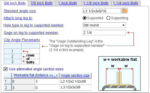
Standard angle size: The angle section size for the specific bolt diameter tab that has been selected. The angle specified here must also be listed in the local shape file .
Attach long leg to: Supported or Supporting .
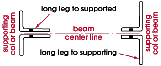
Effect on a full-featured SDS2 program: The selection shown here applies when a " Standard angle size " with unequal legs has been entered (for example, the long leg for L3 1/2x3x5/16 angle material is the leg that is 3 1 /2 inches in length). In a typical situation where a beam frames into a column, the supported member is the beam.
Hole type in leg to supported member: Standard round or Short slot or Long slot or Oversized or User Slot #1 or User Slot #2 .

Effect on a full-featured SDS2 program: The type of hole shown here applies to the clip angle leg that bolts to the supported beam web. A full-featured SDS2 program determines the specific size of a hole based on the " Hole type . . . " shown here and the bolt diameter that is selected as the tab.
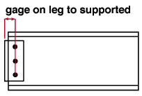
Gage on leg to supported member: The distance (in the primary dimension " Units " or in other units ) from the outside corner of the clip angle to the center of the column of holes on the leg that bolts to the supported beam.
home > project settings > fabricator > pIecemarking > | clip configurations | top
------ Clip angle piecemarks ------
Gage Outstanding Leg: This is the " Gage on leg to supported member " that is entered above. Since there is only one GOL, this table has only a single column.
Effect on a full-featured SDS2 program: Submaterial marks shown here are assigned in a full-featured SDS2 program to double wide/narrow gage clip angles welded to the supporting beam or column according the gage entered above and the number of rows of bolts designated on this table.
home > project settings > fabricator > pIecemarking > | clip configurations | top
------ Alternative angles for welding to supporting members ------
Use alternative angle section sizes: ![]() or
or ![]() . This applies to welded-to-supporting double clip angles. A clip angle that welds to the supporting beam or column is designed when " Attachment to supporting " is set to ' Welded ." Double clip angles are designed when " Side " is set to ' Both ' sides of the web.
. This applies to welded-to-supporting double clip angles. A clip angle that welds to the supporting beam or column is designed when " Attachment to supporting " is set to ' Welded ." Double clip angles are designed when " Side " is set to ' Both ' sides of the web.
In a full-featured SDS2 program . . .
If this box is checked (
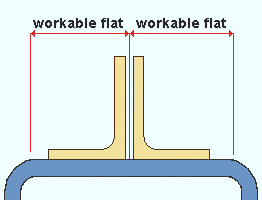
), connection design looks at the workable flat distance on the face of the supporting member that the double clip angles are to be welded to, then selects the angle from the alternative angles table (described below).
If the box is not checked (
), connection design uses the " Standard angle size " that is specified for a particular bolt diameter tab .
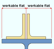
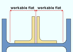
Workable flat distance is greater than or equal to
( >= )Workable flat distance is less than
( < )Angle section size The values in the first column are filled in automatically. They represent the lowest workable flat distance at which the " Angle section size" entered in a particular row will be applied.
The values in the second column can be filled in manually. Each such value represents the largest workable flat distance at which the " Angle section size " entered in a particular row will be applied. The angle to be welded within the workable flat distance on the supporting member. You need to account for the welds and the thickness of the supporting beam's web as well as the angle leg size when determining if the angle will fit in the specified workable flat distance.
home > project settings > fabricator > pIecemarking > | clip configurations | top