The Beam Review window ( Modeling ) (" Status " & " Properties " enabled )
page 1 | contents | review | top
|
|||||
|
|
||||
Section size: The main material of the beam (e.g., ' W12x45 ') . Only materials listed in the local shape file can be specified here.
| Valid Material Types for Beam Connections (A full-featured SDS2 program can generate " Input connection type " connections when the beam's " Section size " is one of these material types.) |
|

|
|
| wide flange ,
channel , welded plate W , S shape |
A full-featured SDS2 program can design the full range of " Input connection types " and can automatically connect braces, beams and columns to a beam whose " Section size " is any of these types. " |
|
HSS/TS (tube) |
A full-featured SDS2 program can design clip angles (perp to W or tube beam/column), shear connections (to tube or channel beam or perp to W or tube column) and end plates (perp to W or tube beam/column). The program can design seats for tube beams, even though field bolting a seat to a tube section can be problematic. Braces, beams and columns can automatically connect to tube beams. |
| welded plate box |
If the " Input connection type " is ' Plain end ', connection design automatically sets back the beam and generates appropriate " |
|
" |
A full-featured SDS2 program can design the full range of " Input connection types ," but cannot apply " Moment " options. |
Note: Beam work lines (stick form member lines) are drawn across the top flange center line of a wide flange , welded plate wide flange or tube beam. For a channel beam, the work line is at the heel of the top flange of the channel.
Status Display: Member status > Member section size
Piecemark or System piecemark or User piecemark or Frozen piecemark :
Sequence :
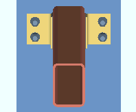
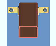
Long side: Vertical or Horizontal . This " ![]() General settings " option applies when the beam's " Section size " is a HSS/TS section.
General settings " option applies when the beam's " Section size " is a HSS/TS section.
|
|
' Vertical ' indicates that the long side is vertical.
' Horizontal ' indicates that the long side is horizontal.
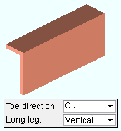
Toe direction: In or Out . This " ![]() General settings " option applies when the beam's " Section size " is channel or single angle material.
General settings " option applies when the beam's " Section size " is channel or single angle material.
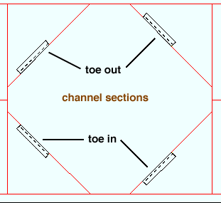
' In ' signifies toe in. ' In ' means the toe(s) of the flange are down in a plan view (toward the right if the workline of the beam is vertical). The toe(s) are toward you if you are facing the near side of the material in an elevation view.
' Out ' signifies toe out. ' Out ' means the toe(s) of the flange point up in a plan view (toward the left if the workline of the beam is vertical). The toe(s) are away from you if you are facing the near side of the material in an elevation view.
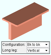
Configuration: Star or Back to back . This " ![]() General settings " option becomes available when the box is checked for "
General settings " option becomes available when the box is checked for " ![]() Double material ."
Double material ."
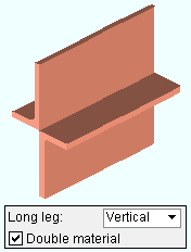
' Star '
|
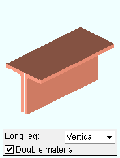
' Back to back '
|
If ' Star ' is selected, the two angles are laid out so that the outside corner of each angle is along the member line of the beam.
If ' Back to back ' is selected, the two angles are laid out so that one leg of each angle is back-to-back. For a non-sloping beam with a " Rotation " of ' 0 ', the top faces of the angles are at the " End elevation " of each end of the beam.
Long leg: Vertical or Horizontal . This " ![]() General settings " option applies when the beam's " Section size " is angle material.
General settings " option applies when the beam's " Section size " is angle material.
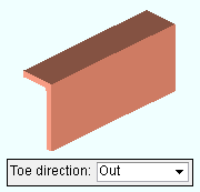
' Vertical '
|
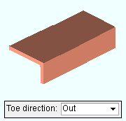
' Horizontal '
|
If ' Vertical ' is selected, the long leg of the angle(s) are vertical when ' 0 ' is entered as the " Beam rotation ."
If ' Horizontal ' is selected, the long leg of the angle(s) are horizontal when ' 0 ' is entered as the " Beam rotation ."
Double material: ![]() or
or ![]() . This "
. This " ![]() General settings " option applies when angle or channel material has been entered as the beam's " Section size ." A full-featured SDS2 program can automatically generate connections on double-channel beams.
General settings " option applies when angle or channel material has been entered as the beam's " Section size ." A full-featured SDS2 program can automatically generate connections on double-channel beams.
 |
 |
If this box is checked (
), two angles (or two channels) are used as the beam main material. The two angles may be either ' Back to back ' or in a ' Star ' " Configuration ." Channels are always back to back.
If the box is not checked (
), a single angle (or channel) is used as the beam main material.
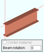
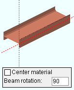
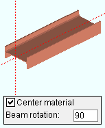
Center material: ![]() or
or ![]() . This "
. This " ![]() General settings " option applies when ' 90 ' when ' -90 ' is the " Beam rotation ."
General settings " option applies when ' 90 ' when ' -90 ' is the " Beam rotation ."
|
|
|
If this box is checked (
), the member main material is centered with respect to the beam work line .
If the box is not checked (
), the top flange of the member is along the beam workline.
Welded section is single material: ![]() or
or ![]() . This "
. This " ![]() General settings " option applies when the beam's " Section size " is a welded plate wide flange or a welded plate box .
General settings " option applies when the beam's " Section size " is a welded plate wide flange or a welded plate box .
|
|
If this box is checked (
) and this beam has been auto detailed in a full-featured SDS2 program , the beam's bill of material lists the welded plate wide flange or welded plate box section as a single section size. A single submaterial detail is drawn to depict the welded plate section.
If the box is not checked (
) and this beam has been auto detailed in a full-featured SDS2 program , the beam's bill of material lists the welded plate wide flange section as three plates (four plates for a welded plate box). Separate submaterial details are drawn for the plates.
If this box is checked (
), the beam is treated as structurally connected to a concrete slab and applies the " Slab width " entered below. A full-featured SDS2 program looks to the Composite Reaction Factor Schedule for a reaction factor. If the reaction factor is ' 1 ', the program uses Beam Composite Design information to calculate the " Shear load ." If the reaction factor is a number other than ' 1 ', the program multiplies that factor times the calculated beam reaction for a noncomposite beam to calculate the " Shear load ."
If the box is not checked (
), this beam is not treated as a composite section for purposes of calculating the " Shear load ."
Also see: Home > Project Settings > Job > Design Settings > " Concrete strength " and " Concrete thickness " are used for composite design.
Status Display: Member status > Composite
Slab width: A distance (in the primary dimension " Units " or in other units ) measured parallel with the beam's Z axis that represents the width of the concrete slab that is supported by this beam. For many cases, this is simply the beam spacing.
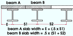
What distance should be entered: For a beam that is not an edge beam, this is the distance between the center lines the adjacent beams divided by two. For an edge beam, this is the smaller of either the distance from the edge of the slab plus half the distance to the adjacent beam, or the distance to the adjacent beam.
Note: If the beam span/4 is smaller than the beam spacing, the beam span/4 should be entered as the " Slab width ." See the ASD 9th Edition Chapter I, Section I1, p 5-56 or the AISC Steel Construction Manual, Thirteenth Edition Section I3.1, p 16.1-83.
Number of studs: The stud count for this beam.
|
In this example of an erection view drawing , the number ' 10 ' was entered as the " Number of studs " for the beams that are shown horizontal. Auto detailing in a full-featured SDS2 program appended the annotation ( S = 10 ) to the section sizes of the beams. |
Effect on erection view detailing: If the user of a full-featured SDS2 program enters a " Number of studs " then auto detail s erection views using the appropriate options, the section size on the erection view drawing will, for this beam, have appended to it (in parentheses) the number of studs that are entered.
No effect on connection design: Unlike the " Slab width ," this count does not affect connection design in any way. In other words, it does not affect how the automatic " Shear load " is calculated. It does not affect any information that is presented in the Connection Design Calculations Report or the Expanded Connection Design Calculations .
Beam rotation: The positive or negative number of degrees of rotation ( 90 to - 90 ) from web vertical. If you are looking along the member workline toward the left end of the member, a positive entry rotates the member counterclockwise that number of degrees.
Rotation = 0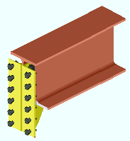 |
Rotation = 90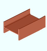 |
' 0 ' (zero) degrees sets the web of the beam to be vertical. The selection made to the " Web rotation " field may override an entry of ' 0 ' shown here if " Hold rotations " is set to ' No ' and this beam frames between sloping beams.
A ' number between +/-90 degrees ' \ is the " Web rotation " for a ' Hip and Valley ' or ' Web Normal ' situation if ' No ' is selected for " Hold rotations ." If ' Yes ' is selected for " Hold rotations ," a number between 0 or 90 is likely a rotation entered by the user of a full-featured SDS2 program , or when the structure was downloaded as a Import Model file.
' 90 ' degrees sets the web of the beam to be horizontal. A full-featured SDS2 program can design only clip angles (to a column web) on a beam that has been rotated 90 degrees.
If this box is checked (
), " Web rotation " is disabled (grayed out) and a full-featured SDS2 program will use the " Beam rotation " that is entered on this window. The box may automatically be checked if Import Model was used to bring members into the 3D model.
If the box is not checked (
), the beam's rotation is set per the " Web rotation " (' Web vertical ' or ' Hip and valley ' or ' Web normal ') or, when " Beam rotation " is ' 90 ', that value will apply.
Rolling operation: None or Camber annotation or Weak axis or Strong axis or Camber or Camber (Both) . The center of curvature for each of these choices (except ' None ' and ' Camber annotation ') is midway between the left and right end of the beam's main material. The work points of the beam are fixed, but the work line (stick form member line) becomes curved as a result of a rolling operation.
' None '

|
' Camber '

|
||||
' Weak axis '

|
' Strong axis '

|
||||
|
|||||
' None ' means the main material is straight, not curved.
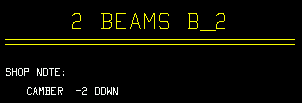
' Camber annotation ' also means the main material is straight, not curved. The value entered as the " Mid-ordinate " is added as a shop note to this beam's detail. A negative (-) " Mid-ordinate " makes the annotation indicate that distance down. A positive " Mid-ordinate " indicates up. The same " Mid-ordinate " value is added to the " Remarks " column in the member bill of material if " Show camber on the bill of material " is checked (in setup).
' Strong axis ' or ' Weak axis ' indicates circular rolling. The " Mid-ordinate " or " Included Angle " or " Rolling radius " sets the offset at mid-span and the direction (+ or -) of that offset.
' Camber ' produces parabolic bending along the strong axis of the rolled section with the ends fixed. The " Mid-ordinate " sets the offset at mid-span and the direction (+ or -) of that offset.
' Camber (Both) ' combines ' Camber annotation ' with ' Camber '. The beam is shown as curved in the 3D model and on the member detail. You also get the camber annotation on the beam detail.
Status Display: Member status > Rolling operation
Mid-ordinate: The positive or negative (-) distance (in the primary dimension " Units " or other units ) that the beam's main material is offset at mid-span as a result of a " Rolling operation " of ' Strong axis ' or ' Weak axis ' or ' Camber ' or ' Camber (both) '. The sign (+ or -) sets the direction of offset.
Camber with a positive mid-ordinate ( +m )
 |
Camber with a negative mid-ordinate ( -m )
 |
| Weak axis rolling with a positive mid-ordinate ( rolling toward the near side )  |
Weak axis rolling with a negative mid-ordinate ( rolling toward the far side )  |
Strong axis rolling with a positive mid-ordinate ( +m )
 |
Strong axis rolling with a negative mid-ordinate ( -m )
 |
Status Display: Member status > Mid-ordinate
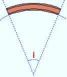
Included angle: The positive or negative (-) number of degrees that the beam is curved a result of a " Rolling operation " of ' Weak axis ' or ' Strong axis '. In the following example, ' Strong axis ' rolling is shown:
|
i = included angle. Extrapolate a circle from the inside curvature of the beam's main material, then draw a line along each end of the main material. The lines will meet at the center of the imaginary circle, and their included angle is the angle entered here. |
Note: The strong axis or weak axis rolling that takes place when an " Included angle " is entered is the same circular rolling that takes place when " Mid-ordinate " is entered. The rolling is circular, and the work points of the beam do not change.
Status Display: Member status > Included angle
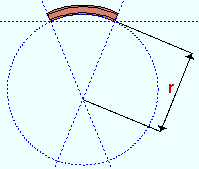
Rolling radius: The positive or negative distance (in the primary dimension " Units " or other units -- up to +/- 120,000 inches) that the beam's edge is from the center of the radius of bending as a result of a " Rolling operation " of ' Weak axis ' or ' Strong axis '. The smaller the " Rolling radius " (+ or -), the greater the curvature.
|
r = rolling radius. If you were to extrapolate a circle from the inside curvature of the beam's main material, the distance from any point on the inside curve of the top/bottom flange to the center of the circle is the distance entered here. |
Note: The strong axis or weak axis rolling that takes place when a " Rolling radius " is entered is the same circular rolling that takes place when a " Mid-ordinate " is entered. The rolling is circular, and the work points of the beam do not change.
Status Display: Member status > Rolling radius
Spiral offset: The positive or negative (-) distance (in the primary dimension " Units " or other units ) that the right end of the beam is offset from its right-end work point (wkpt 2 in the example). The left end work point of the beam remains fixed. This " ![]() General settings " option applies when the " Rolling operation " is ' Weak axis ' or ' Strong axis '.
General settings " option applies when the " Rolling operation " is ' Weak axis ' or ' Strong axis '.

For both ' Weak axis ' and ' Strong axis ' rolling: The work line (stick form member line) and beam main material reflect the offset. The rolling remains circular.
For ' Weak axis ' rolling: A positive offset raises the elevation of the workline at its right-end point the exact distance that is entered. A negative offset lowers the elevation of the workline at its right-end point. For either sign, the beam's right " End elevation " remains the same.
For ' Strong axis ' rolling: A positive offset offsets the workline at its right-end point the exact distance that is entered; the workline is offset in the direction of the near side of the beam. A negative offset offsets the workline in the direction of the far side of the beam.
Status Display: Member status > Spiral offset
------------------
![]() or
or ![]() member general information settings:
member general information settings:
Main material Model complete Marked for processing Model complete date Marked for detailing Lift assignment Node-match job
------------------
WP to WP length, plan: The work point-to-work point distance spanned by the beam workline in a plan view, ignoring elevation. This " ![]() General settings " distance is calculated from the X and Y (but not Z) global coordinates of the beam work points.
General settings " distance is calculated from the X and Y (but not Z) global coordinates of the beam work points.
If the beam is sloped out of the plan view elevation, the value show here is not the actual work point-to-work point length, but rather the distance from column line to column line (grid line to grid line) as measured at a single elevation.
WP to WP length, actual: The actual length of the beam workline . This " ![]() General settings " distance is calculated from the X and Y and Z global coordinates of the beam work points.
General settings " distance is calculated from the X and Y and Z global coordinates of the beam work points.
This distance minus any " Setbacks " that have been applied is the actual length of the beam. The maximum work point to work point length for which you can reliably obtain system connections is 80 feet.
page 1 | contents | review | top
|
|||||
|
|
||||
Seismic moment frame member: Automatic or Yes or No . This option affects the design (in a full-featured SDS2 program ) of ' Welded ' and ' Bolted ' beam-to-column-flange moment connections that are specified in the " ![]() Moment " leaf on either or both ends of this beam.
Moment " leaf on either or both ends of this beam.
| ' Yes ' or, possibly, ' Automatic ' | ' No ' or, possibly, ' Automatic ' |
| • The choice made to " Seismic moment frame type " (' OMF ' or ' IMF ' or ' SMF ') governs seismic moment connection design. |
• Moment connections can still be designed per choices made in the " |
| • When " Moment type " is ' Welded ' or ' Bolted ', the " Panel zone moment load " governs the design of seismic moment connection web doublers. | • Moment web doublers are designed without regard to the " Panel zone moment load ." |
| • When " Moment type " is ' Non-moment ', a seismic moment connection cannot be designed. | • When " Moment type " is ' Non-moment ', no moment connection can be designed. |
|
• When " Moment type " is ' Welded ', " Re-entrant cut " and " Groove angle " are disabled in the " |
• When " Moment type " is ' Welded ', " Re-entrant cut " and " Groove angle " are enabled . An ' Alternate 3 ' or ' Alternate 1 ' moment connection is designed. |
|
• The " |
• The " |
In a full-featured SDS2 program . . .
' Automatic ' specifies that connection design apply a setup choice ( Home > Project Settings > Job > Design Settings > " Seismic moment connection design " >
or
). If that box is checked and this end connection's " Moment type " is ' Welded ' or ' Bolted ', connection design creates a seismic moment connection. If it is not checked, connection design does not create a seismic welded moment connection.
' Yes ' instructs connection design to attempt to design a seismic moment connection based on the selected " Seismic moment frame type " (' OMF ' or ' IMF ' or ' SMF '). To get a connection, " Moment type " needs to be ' Bolted ' or ' Welded '. ' OMF ' or ' IMF ' seismic moment connections can be designed when the " Connection design method " is any LRFD edition. ' OMF ' seismic moment connections can be designed for LRFD and ASD editions.
' No ' instructs connection design to design non-seismic welded and bolted moment connections based on choices made in the "
Moment " leaf.
Note: Seismic welded moment connections are designed based on the " Seismic Access Hole " designation (' A ' or ' B ' or ' C ' or etc.) that is entered in the local shape file for the " Section size " of the beam. Connection design references Home > Project Settings > Job > Seismic Weld Access Holes to determine the size and shape of the access hole. If the local shape file's " Seismic Access Hole " designation is ' None ' for the beam's " Section size ," then connection design does not reference the Seismic Weld Access Holes setup window, but instead uses the setup values defined for moment connections at Home > Project Settings > Job > Weld Design Settings . A back-up bar may optionally be included as part of the seismic connection, per the setup instructions entered at Home > Project Settings > Job > Moment Plate Design Settings > the " Back-up Bars on Welded Connections " tab > " Create solids for seismic connections ."
Seismic moment frame type: Automatic or OMF or IMF or SMF . This applies when " Seismic moment frame member " is set to ' Yes ' or, possibly, to ' Automatic '. ' IMF ' and ' SMF ' seismic moment connections can be designed when the " Connection design method " is any LRFD edition. ' OMF ' seismic moment connections can be designed for LRFD and ASD editions.
' Automatic ' specifies that connection design apply a setup choice ( Home > Project Settings > Job > Design Settings > " Seismic moment frame type " > ' OMF ' or ' IMF ' or ' SMF ' ). For example, if that option in Design Settings is set to ' IMF ', then connection design will use IMF design for the seismic moment connection.
' OMF ' stands for "Ordinary Moment Frame." OMF connections provide less resistance to lateral motion than do IMF or SMF frames and are only recommended for non-seismic or low seismic regions. When the " Connection design method " is ' LRFD 15 ' or ' ASD 15 ', only welded moment shear tab connections can be designed.
' IMF ' stands for "Intermediate Moment Frame." IMF connections are designed to be installed in moderate seismic regions.
' SMF ' stands for "Special Moment Frame." SMF connections are designed to resist flexural, axial, and shearing actions that result as a building sways through multiple inelastic displacement cycles due to a strong earthquake.
End connection failure message: IMF/SMF connections not supported for ASD
End connection failure message: Seismic moment connection is not prequalified
End connection failure message: Seismic moment connection only allowed to column flange
End connection failure message: Only welded flange OMF supported for 15th edition
End connection failure message: IMF/SMF flange bolt design valid only for A490/F2280 bolts
End connection failure message: IMF/SMF flange hole type must be standard round
End connection failure message: IMF/SMF maximum flange bolt diameter is 1 1/8 inch
End connection failure message: IMF/SMF connections must have matching load auto flags
Story height above node : The distance (in the primary dimension " Units " or other units ) from the half-depth of this beam to the half-depth of the beam above. See figure 4-26(a) on page 4-123 of the 3rd Edition Seismic Manual.
After making the appropriate entry here, a user in a full-featured SDS2 program could enter the " Story height below node " (below) and follow steps 1 - 4.
Story height below node : The distance (in the primary dimension " Units " or other units ) from the half-depth of this beam to the half-depth of the beam below.
After making an entry here and above, and after the connedtion passes, the user of a full-featured SDS2 program could do the following:
1. Press the " Design Calcs " or " Expanded Calcs " button at the bottom of this window.
2. Based on the entry you make here and to " Story height above node " (above) and on the appropriate end's " Panel zone moment load ," connection design will calculate the story shear force, Vc , and report the result in the design calculations (either report). The result is output to the report instead of this edit window because, currently, there is no " Auto " check box for " Story load ."
3. Manually enter the story load shown in the report to "
Loads " > " Story shear " for the appropriate end of this beam.
4. Connection design will re-design the connection factoring in the " Story shear " that you entered.
Uniformly distributed gravity load (kips or kN) : A user-entered load in kips (kilonewtons for ' Metric '). Unlike the left- and right-end " ![]() Loads " found on this window, this uniformly distributed gravity load applies to the entire beam.
Loads " found on this window, this uniformly distributed gravity load applies to the entire beam.
The value entered here affects the "
Auto " calculation of the " Panel zone moment load " for the end(s) of this beam that have an ' IMF ' or ' SMF ' welded or bolted seismic moment connection.
The " Panel zone moment load " affects the design of seismic moment connection web doublers.
page 1 | contents | review | top
|
|
| Determining a member's left end : |
| Look at the location of its piecemark (B_2). |
|
Look at its reference point ( |
| The left end is related to global coordinates . |
| Left end of a member in a plan view . |
| Left end of members in an elevation view . |
indicates that, in a full-featured SDS2 program , all options are disabled ( grayed out ) under [ Left end settings ] or [ Right end settings ] , thus preventing users from making changes to the end connection. To preserve the connection, users of that program are also prevented from manually editing or cutting or deleting connection materials on the locked end of the member.
indicates that a user of a full-featured SDS2 program is allowed to edit the options under [ Left end settings ] or [ Right end settings ] .
Status Display: Approval and modeling > Member end locked
page 1 | contents | review | top
|
|
|||||||||
|
|
||||||||
Connection: Force and/or Graphical . This " ![]() Information " option applies when this beam end's " Input connection type " is a choice other than ' Plain end '.
Information " option applies when this beam end's " Input connection type " is a choice other than ' Plain end '.
' Force ' indicates a failed connection has been forced to be designed in a full-featured SDS2 program , even though the design may be ill advised from an engineering standpoint.


forced 

system The Connection Design Calculations report (and Expanded Connection Design Calculations ) include a warning that the connection has been forced.
' Graphical ' indicates that the connection on this end of the member is graphical and, therefore, will not be changed during connection design in a full-featured SDS2 program .


graphical 

system The Connection Design Calculations report (and Expanded Connection Design Calculations ) include the warning " GRAPHICAL CONNECTION -- STRENGTH CALCULATIONS NOT GENERATED ."
Status Display: Search > Graphical connections
Search: Graphical Connections
" Connection design lock set ," connection failure messages , other messages:
The following banner notifies you that the connection has at least one "
Connection design lock " or "
End preparations " setting that is locked (
):
Connection design locks set.
VIDEO 
Sections (" leaves ") within which at least one locked variable resides are marked (in the navigation tree) with a locked icon ( ). (Recorded in SDS2 Detailing , v2015.)
Search: Connection design locks set
Status Display: Search > Connection design locks setYou may find a red connection failure banner like that shown below along with a
button. The button doesn't do anything in SDS2 Site Planning. In a full-featured SDS2 program, the button provides context-sensitive help about the message.
| Beam web shear capacity failed |
Or you may find a green " Connection changed ... " banner which indicates that, in order to make the connection work, connection design has deviated from the connection specifications entered by the user in a full-featured SDS2 program . Tip: Compare the " Summary ," the " Input connection type ," the " System designed connection " and the "
Connection specifications " to assess what has changed. Also see: Search for Connections Changed by System .
| Conn changed. Possibly: Angle vs Plate |
If you are reviewing multiple beams and those beams have different connection changed or connection failure messages, you get a banner like the following:
| Multiple connection messages |
page 1 | contents | review | top
|
|
|||||||||||
|
|
||||||||||
"
Member " settings are separated for the right and left end of the beam.
If two different " End elevations " are entered, the beam will be sloping.
If different " Web rotations " are selected, the beam may be twisted.
End elevation: The elevation of the work point at this end of the beam. For a non-sloping beam, this is the elevation of the top flange of the beam.
Tip: To determine the end elevation on a beam while working in the 3D model, use Construction Line Add or a similar tool, select EXPT as the Locate option, then move the point location target to the work point at the end of a beam and reference the Z coordinate reported in the X-Y-Z display .
Web rotation: Automatic or Web vertical or Hip and valley or Web normal . This " ![]() Member " option applies when " Hold rotations " is set to ' No ' and when " Beam rotation " is not ' 90 '. For beam-to-column framing conditions, ' Web Vertical ' should be selected. For perpendicular beam-to-horizontal beam framing conditions, any of the four choices give the same results. For skewed beam-to-sloping beam framing conditions, see below:
Member " option applies when " Hold rotations " is set to ' No ' and when " Beam rotation " is not ' 90 '. For beam-to-column framing conditions, ' Web Vertical ' should be selected. For perpendicular beam-to-horizontal beam framing conditions, any of the four choices give the same results. For skewed beam-to-sloping beam framing conditions, see below:
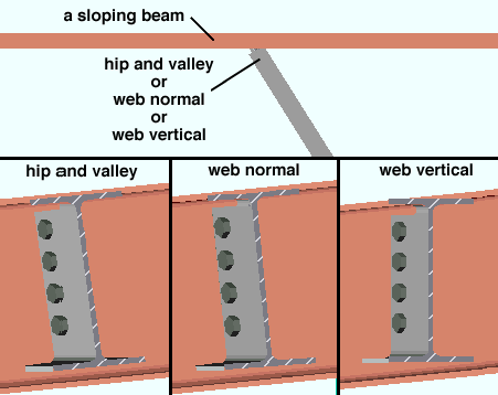
' Automatic ' causes the selection made here to be made automatically in a full-featured SDS2 program .
' Web vertical ' makes the web of the beam vertical to the world.
' Hip and valley ' instructs the program to rotate the web of the beam to keep the flange of the beam being input in the same plane as the flange of the sloping beam it is framing into.
' Web normal ' instructs the program to rotate the web of the beam being input as needed to keep the CONNECTION in the beam perpendicular to the flange of the sloping beam it is framing into.
Example: The user of a full-featured SDS2 program frames a beam into a sloping beam to form a roof support. The other end of the beam has a plain end and frames into concrete. For the framing end, the user selects ' Web Normal '. For the opposite end, the user selects ' Automatic ' in order to keep the beam from being twisted.
page 1 | contents | review | top
|
|
|||||||||
|
|
||||||||
Input connection type: Auto standard or User defined or Plain end or Bearing or Clip angle (" Moment " options can also be added) or Bent plate (" Moment " options can also be added) or End Plate (" ![]() Moment " options can also be added) or Shear ("
Moment " options can also be added) or Shear (" ![]() Moment " options can also be added) or Seated (N/A for tube beams) or Splice plate (N/A for HSS beams) or Fully welded moment (automatically sets " Moment type " to ' Welded ').
Moment " options can also be added) or Seated (N/A for tube beams) or Splice plate (N/A for HSS beams) or Fully welded moment (automatically sets " Moment type " to ' Welded ').
| Input connection | Comments |
| ' Auto standard ' | A connection that is designed based on the beam's framing condition . Auto standard connections have a number of advantages . |
| ' User defined ' | The name of the user defined connection is entered to " User defined connection " (below). |
| ' Plain end ' | The program automatically copes and sets back a ' Plain end ' beam to a beam or column. See " Plain end " on the Field Clearances job setup window. |
| ' Bearing ' |
An " Embed schedule entry " may result in a bearing plate / angle / channel to a concrete wall or panel. Locks in the " |
| ' Clip angle ' or ' Bent plate ' or ' End plate ' or ' Shear ' or ' Seated ' or ' Splice plate ' |
Select " |
| ' Clip angle ' or ' Bent plate ' or ' End plate ' or ' Shear ' or ' Splice plate ' |
" |
| ' Clip angle ' or ' Bent plate ' or ' End plate ' | Connections of these types can be created even when the end of the beam does not frame to another member. |
| ' Bearing ' or Clip angle ' or 'Bent plate ' or ' Shear ' or ' Seated ' or ' Plain end ' | For a beam that frames to concrete, an " Embed schedule entry " may have been made in order to create a connection. For a ' Plain end ', no connection is created, but the embed is still added to the wall. |
| ' Fully welded moment ' |
The " Moment type " is ' Welded " and a clip angle or shear plate or bent plate is not a part of the connection. The web of the wide flange or similarly shaped beam welds directly to the column. Some " |
Design of the " Input connection type " that is specified here takes place in a full-featured SDS2 program .
"
Connection specifications " and connection design locks also relate to a connection's design.
The " Design Calc " or " Expanded Calc " button on this window gives you the connection's design calculations.
User defined connection: The file name of the user defined connection in your current Job that has been applied to this end of the beam.
This "
Connection type " option applies when this beam end's " Input connection type " is ' User defined '.
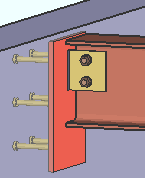
Embed schedule entry: A standard piecemark name from the " Piecemark " column in the Embed Schedule . This " ![]() Connection type " option applies when the " Input connection type " is ' Clip angle ' or ' Shear ' or ' Bent plate ' or ' Seated ' or ' Plain end ' or ' Bearing ' and the beam frames to a concrete wall .
Connection type " option applies when the " Input connection type " is ' Clip angle ' or ' Shear ' or ' Bent plate ' or ' Seated ' or ' Plain end ' or ' Bearing ' and the beam frames to a concrete wall .
|
|
|
|
An embed plate from the Embed Schedule . In this example, the " Input connection type " is ' Shear '. A similar connection is created when the " Input connection type " is ' Clip angle ' or ' Bent plate '. For ' Seated ', the embed plate is also vertical, but placed lower down with respect to the beam. For ' Plain end ," there is no connection to the embed plate. |
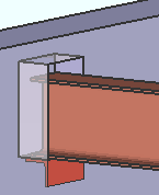
|
An embedded bearing angle from the Embed Schedule . The " Input connection type " is ' Bearing'. By default, SDS2 connection routines automatically match the length of the angle to the width of the pocket that is created in the concrete wall. J ob Setup > Field Clearances > " Steel to concrete " clearances apply to the pocket. |
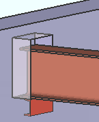
|
An embedded bearing channel from the Embed Schedule . The " Input connection type " is ' Bearing'. The length of the channel matches the width of the pocket. The " Side " erection clearance in the " |
System designed connection: The type of connection designed on this end of the beam (e.g. ' Clip angle ' or ' Bent plate ' or ' Moment end plate ' or ' End plate ' or etc.).
The type of connection reported here is different than the connection reported to " Input connection type " when the connection has failed, or connection design has changed the connection type, or if ' User defined ' or ' Auto standard ' is the selected " Input connection type ."
NM bolt type to supported: Auto or A325N or A325SC or A325X or etc. NM stands for "non-moment." This " ![]() Connection type " option sets the type of non-moment bolt used to fasten connection material to the supported member (to this beam). If the connection is a bolted moment connection, users of a full-featured SDS2 program can additionally apply a moment " Bolt type " for bolting the flange plates ( Exception: moment end plates take moment bolts only). For certain connection types, those users may apply a " NM bolt type to supporting " instead of or in addition to a " NM bolt type to supported ."
Connection type " option sets the type of non-moment bolt used to fasten connection material to the supported member (to this beam). If the connection is a bolted moment connection, users of a full-featured SDS2 program can additionally apply a moment " Bolt type " for bolting the flange plates ( Exception: moment end plates take moment bolts only). For certain connection types, those users may apply a " NM bolt type to supporting " instead of or in addition to a " NM bolt type to supported ."
When " Auto " is checked (
), the non-moment connection on this end of the beam is designed (in a full-featured SDS2 program ) using the default " Bolt type " for non moment connections set in Bolt Settings . For auto standard connections, the program uses the " NM bolt type " entered in Auto Standard Connections .
When " Auto " is not checked (
), the user-specified type of bolt that is shown here will be used in the design of the non-moment connection on this end of the beam.
NM bolt type to supporting: Same as " NM bolt type to supported ," except that this applies to bolts that fasten the connection material to the supporting member. The supported member is this beam. The supporting member is the column or beam that this beam frames to. The table below explains, by connection type, when this field applies or does not apply.
| Input
connection type |
NM bolt type | |
| to supported | to supporting | |
| auto standard | applies | applies |
| user defined | applies | applies |
| clip angle | applies | applies |
| bent plate | applies | applies |
| end plate | does not apply | applies to non-moment end plates only |
| shear plate | applies | does not apply |
| shear tee | applies | applies |
| seated beam | applies | applies |
| splice plate | applies | does not apply |
Moment end plates take moment bolts only. When the " Input connection type " is ' End Plate ' and the " Moment type " is ' Bolted ', only the " Bolt type " for moment connections is used.
NM bolt diameter: Auto or a user-entered diameter .
| diameter |
|
When " Auto " is checked (
), the default " Bolt diameter " for non-moment connections set in Bolt Settings is used for non-moment connection on this end of the beam. For auto standard connections, the " NM bolt diameter " set in Auto Standard Connections is used.
If " Auto " is not checked (
), the user-specified bolt diameter that is shown here is the minimum diameter used in the design of the non-moment connection on this end of the beam.
Note: For clip angles, shear connections, end plates, bent plates and splice plates, connection design in a full-featured SDS2 program may increment the user-input " NM bolt diameter " to a larger diameter (of the same units) if that diameter is checked (
) at Home > Project Settings > Job > Bolt Settings > " Available bolt diameters ."
Use miscellaneous plates list: ![]() or
or ![]() .
.
If this box is checked (
), design routines in a full-featured SDS2 program look to Home > Project Settings > Fabricator > Standard Fabricator Connections > Plates to determine the plate thicknesses to be used for plates on the connection for this end of the beam.
If the box is not checked (
), those same design routines round the calculated required thickness of plates as based on the load to the next 1/16 inch (or 1/8 inch if the calculated required thickness is greater than 5/16 inch).
Exceptions and related settings: " Standard Shear Plate Settings " sets shear plate thicknesses. " Design non-AISC single-plate shear connections " sets shear plate thicknesses. " Minimum doubler plate thickness " affects column web doubler plates for moment connections.
Use a safety erection seat: ![]() or
or ![]() .This "
.This " ![]() Connection type " option applies to ' Non-moment ' clip angle , bent plate , end plate and shear connections on wide flange beams framing to a W column.
Connection type " option applies to ' Non-moment ' clip angle , bent plate , end plate and shear connections on wide flange beams framing to a W column.
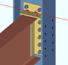 |
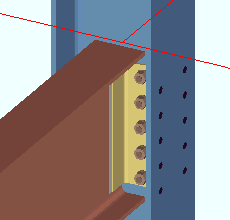
|
When this box is checked (
), connection design creates an angle seat on the ( top or bottom ) flange of the supported beam. In the Design Calculations Report and Expanded Connection Design Calculations Report , the size and orientation of the safety seat are noted, but the existence of the safety seat is not figured into any limit state or load capacity calculations for the connection.
If the box is not checked (
), a safety seat is not designed for this connection.
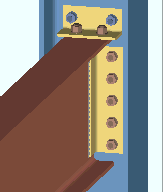
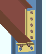
Location of safety erection seat: Top or Bottom . This " ![]() Connection type " option applies when the box for " Use a safety erection seat " is checked.
Connection type " option applies when the box for " Use a safety erection seat " is checked.
|
|
|
| Bottom |
' Top ' specifies that connection design (in a full-featured SDS2 program ) creates an erection angle that bolts to the top flange of the supported beam (the beam whose edit window this field appears on). If ' On column ' or ' Ship loose ' is selected in Fabricator Setup > Connection Detailing/Fabricator Options > " Show field bolted stability angles ," the angle is detailed on the column. If ' On beam ' is selected for " Show field bolted stability angles ," the angle is detailed on the beam.
' Bottom ' instructs the program to bolt the seat to the bottom flange of the supported beam. The seat is detailed on the column. Setup: " Gap for safety seat on bottom flange ."
Safety erection seat gap: Auto or a user-entered distance (inches or mm). This " ![]() Connection type " option applies when the " Location of safety erection seat " is set to ' Bottom '.
Connection type " option applies when the " Location of safety erection seat " is set to ' Bottom '.
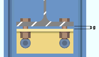
|
g = gap between the safety seat and the bottom flange of the beam. |
If " Auto " is checked (
), the program uses the " Gap for safety seat on bottom flange " that is set Connection Erectability Settings (setup).
If " Auto " is not checked (
), the distance shown here (in the primary dimension " Units " or other units ) was entered by the user of a full-featured SDS2 program .
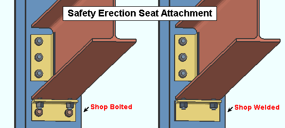
Attachment: Automatic or Bolted or Welded . This " ![]() Connection type " option applies when the box for "
Connection type " option applies when the box for " ![]() Use a safety erection seat " is checked.
Use a safety erection seat " is checked.
In a full-featured SDS2 program . . .
' Automatic ' specifies that connection design shop weld or shop bolt the safety erection seat to the supporting column based on a setup choice ( Home > Project Settings > Fabricator > Connection Erectability Settings > " Safety erection seat connection to supporting ").
' Bolted ' instructs connection design to shop bolt the safety erection seat to the column. If ' Bolted ' is selected for a beam to an HSS/TS column, connection design does not fail the connection but instead gives you the same results as you would get if you had selected ' Welded '.
' Welded ' instructs connection design to shop weld the seat to the column.
Provide minimum cope depth : Automatic or Yes or No . This " ![]() Connection type " option applies to copes generated for beam-to-beam framing conditions when the connection is, for example, a clip angle, shear plate, bent plate or end plate.
Connection type " option applies to copes generated for beam-to-beam framing conditions when the connection is, for example, a clip angle, shear plate, bent plate or end plate.
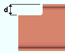
|
d = cope depth. |
' Automatic ' instructs connection design (in a full-featured SDS2 program ) to create the connection on this end of the beam based on the choice made to " Provide minimum cope depth " in Member Detailing Settings (setup).
' Yes ' instructs the program to ignore the k distance of the supporting member when calculating the depth of the cope. This will provide a cope of minimum depth.
' No ' instructs the program to cope the supported beam so that it clears the k distance of the supporting member.
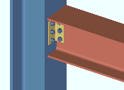
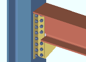
Minimum setup connection: Automatic or Yes or No . The Connection Design Calculations and Expanded Connection Design Calculations report the connection strength for various limit states in either case.
' Yes '
|
' No '
|
' Automatic ' instructs the program to design the connection on this end of the beam based on the choice made to the " Minimum setup connection " field in Design Settings .
' Yes ' instructs connection design to create the connection on this end of the beam with the minimum number of bolt rows, the minimum plate thickness, etc. A green banner in the "
Loads " section of this window informs users that the connection has been designed with the " Minimum setup connection capacity ."
' No ' instructs connection design to create the connection on this end of the beam to meet loading conditions derived from calculated values (Auto entries) or user-entered values made to "
Loads " on this window.
Disable framing situation checks: ![]() or
or ![]() . The choice made here does not affect this program. Framing situation checks are not done in SDS2 Site Planning.
. The choice made here does not affect this program. Framing situation checks are not done in SDS2 Site Planning.
If this box is checked (
), framing situation checks are turned off.
If the box is not checked (
), the framing situation checks are turned on.
page 1 | contents | review | top
|
|
|||||||||
|
|
||||||||
There are no "
Connection specifications " options when the " Input connection type " is ' Auto Standard ' or ' User Defined ' or ' Plain end '.
For more information, click on a link :
| Clip angle (" |
|
| Gage | Use expanded vertical bolt spacing |
| Attachment to supported | Welded extended tee |
| Attachment to supporting | Full depth extended tee |
| Side | Flange splice plates on |
| Attached to | Replace doubler with larger clip |
| Use erection bolts ( | Use paddle plate |
| Safety connection | Skew holes in angle |
| Extend past flange | Combine beam/vbrc clip angles |
| Create web doublers | Check supporting member for axial load |
| Stagger on | Embed plate location |
Bent plate
(" ![]() Moment " options can be added)
Moment " options can be added)
| Gage | Stagger on |
| Attachment to supported | Welded extended tee |
| Attachment to supporting | Full depth extended tee |
| Side | Bent plate grade |
| Attached to | Use paddle plate |
End plate
(" ![]() Moment " options can be added)
Moment " options can be added)
| Gage | Combine beam/vbr end plates |
| Safety connection | Welded extended tee |
| Expanded vertical bolt spacing | Full depth extended tee |
| Extend plate to beam flanges | Check supporting for axial load |
| Extension dimension | End plate grade |
Shear
(" ![]() Moment " options can be added)
Moment " options can be added)
| Material type | Use expanded vertical bolt spacing |
| Attachment | Combine beam/vbr shear plates |
| Attached to | Try two bolt column shear tabs |
| Shear plate/tee side | Use paddle plate |
| Flange splice plates | Skew holes in plate |
| Support condition | Use back-up bar |
| Thru shear plate | HSS column reinforcement |
| Weld split plate to thru plate | Use alternate eccentricity |
| Extend past flange | Check supporting for axial load |
| Extend stabilizer plates | Shear plate grade |
| Stiffener opposite | Embed plate location |
| Extend size to | Bevel shear plate as required |
| Seat material | Seat to supporting member |
| Stability angle | Seated plate grade |
| Location | Embed plate location |
Splice plate (bm-to-bm)
(" ![]() Moment " options can be added)
Moment " options can be added)
| Web plates on | Splice plate grade |
| Web plate side | Flange plates on |
page 1 | contents | review | top
|
|
|||||||||
|
|
||||||||
" Setback " options are divided into " Left End Settings " and " Right end settings " settings. See the topic " Determining left end & near side " if you are unsure which end of this beam is which.
Field clearance: The distance (in the primary dimension " Units " or in other units ) from the face of connection to the face of the supporting member.
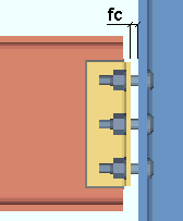
|
fc = field clearance |
Status Display: Member status > Left end field clearance
Input minus dimension: A positive or negative (-) distance (in the primary dimension " Units " or in other units ) measured parallel with the workline of the beam from the beam's work point to the face of the connection on the end of the beam. If the beam is sloping, the actual sloped minus dimension must be calculated and entered.
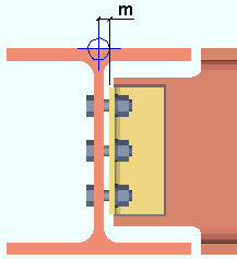
|
m = minus dimension. |
A ' positive minus dimension ' shortens the beam by that amount.
A ' negative (-) minus dimension ' makes the beam longer.
Status Display: Member status > Left end minus dimension
Automatic minus dimension: A calculated distance . If this option is selected, then a full-featured SDS2 program will calculate the half-web or half-depth of the member being framed into and add the field clearance and round up to the nearest 1/16 inch to set the minus dimension.
Status Display: Member status > Auto minus dimension (either end)
Status Display: Member status > Left end minus dimension
Connection setback: The distance (in the primary dimension " Units " or in other units ) from the face of the connection to the end of the supported beam when a clip angle or bent plate is the connection type on this end of the beam.
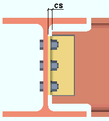
|
cs = connection setback |
Status Display: Member status > Left end connection setback .
Input material setback: The distance (in the primary dimension " Units " or in other units ) measured parallel with the workline of the beam from the work point for this end of the beam to the cut end of the main material. This " ![]() Setbacks " option applies when ' Plain end ', ' Clip angle ' or ' Bent plate ' or ' User connection ' is the connection on this end of the beam.
Setbacks " option applies when ' Plain end ', ' Clip angle ' or ' Bent plate ' or ' User connection ' is the connection on this end of the beam.
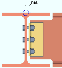
|
ms = material setback |
Status Display: Member status > Has input setback
Status Display: Member status > Left end material setback .
Automatic material setback: The distance (in the primary dimension " Units " or in other units ) measured parallel with the workline of the beam from the work point at this end of the beam to the cut end of the main material.
Status Display: Member status > Auto material setback (either end)
Status Display: Member status > Left end material setback
Standard detail: None or the file name of a job standard detail or global standard detail .
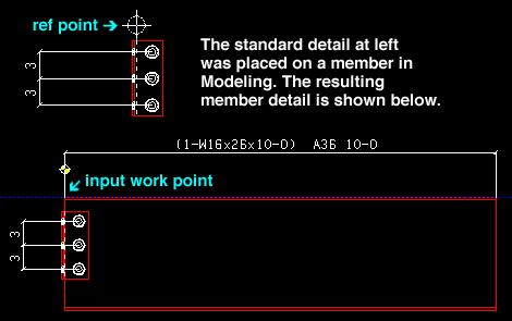
If ' none ' is shown here, then no standard detail will be applied on this end of the beam when this beam is automatically detailed .
If a ' standard detail name ' is shown here, the next time this beam is automatically detailed in a full-featured SDS2 program , the reference point of the standard detail will align with the input work point on this end of the beam, and the standard detail's bill of material will be combined with the beam's bill of material.
page 1 | contents | review | top
|
|
|||||||||
|
|
||||||||
|
| Moment type | Use inner flange plates | Re-entrant cut |
| Design for doublers | End plates | Groove angle |
| Design for stiffeners | Location | Haunch location |
| Col web dblr side | Bolt pattern | |
| Connection material | Bolt type | |
| Connection type | Bolt diameter |
Note: For "
Moment " options to be applied, ' End plate ' or ' Shear ' or ' Clip angle ' or ' Splice plate ' or ' Fully welded moment ' must the " Input connection type " for this end of this beam.
page 1 | contents | review | top
|
|
|||||||||
|
|
||||||||
Warning: When Auto is not checked for a particular type of load, then the user of a full-featured SDS2 program has entered a load. Users should make entries to load fields only at the direction of a qualified engineer.
| A banner like the following is shown here when the connection on this end of the beam is a " Minimum setup connection ." |
| Minimum setup connection capacity |
Shear load (kips or kN): Auto or a user-entered load in kips (kilonewtons for " Metric "). The shear end reaction shown here is used in the design of the " System designed connection " on this end of the beam if that connection is a clip angle, bent plate, end plate, shear, seated beam or beam splice.
| Shear load: |
|
|
| or | ||
| Shear load: |
|
|
When " Auto " is checked (
), connection design calculates the shear end reaction on this end of the beam at the percent of uniform allowable load or maximum web shear entered as the " Beam design reaction " in Design Settings . The calculated numerical value -- calculated in this example -- is the actual value that is used to design the connection on this end of the beam.
When " Auto " is not checked (
), a user of a full-featured SDS2 program has set the load. The user-entered value is used to design the connection.
Also see: A special search for beams with Shear Loads Below Minimum Setup exists to help you find any user-input shear end reactions that are less than that which the program would have determined.
Status Display: Member status > Left end shear load and Right end shear load
Status Display: Connection auto loads > Auto beam shear
Story shear (kips or kN): 0 (zero) or a user-entered load in kips (kilonewtons for ' Metric ').
' 0 ' (zero) specifies that story load not be used in design of a beam-to-column flange moment on this end of the beam.
A ' user-entered load ' applies to the design of the connection on this end of a beam if this end of the beam frames to a column flange and " Moment Specifications " have been applied.
Status Display: Member status > Left end story shear and Right end story shear
Moment load ( kip-in or kip-ft or kN.m): Auto or a user-entered load (in kip-in or kip-ft for ' Imperial ', kilonewton-meters for ' Metric '). The moment shown here is used in the design of the connection on this end of the beam if " ![]() Moment " specifications have been applied.
Moment " specifications have been applied.
| Moment load: |
|
|
| or | ||
| Moment load: |
|
|
When " Auto " is checked (
), connection design determines the moment for this end of the beam at the " Percent of maximum allowable moment " entered in Design Settings . The calculated numerical value -- calculated in this example -- is the actual value that is used to design the connection on this end of the beam. The sign of the left end moment defaults to positive and that of the right end defaults to negative. This is the usual case for gravity loading. For other conditions, such as wind load, the signs may be changed by the user. Design method considerations: For ' ASD ' or ' LRFD ', the "
Auto " moment load is calculated per Section F2.1. For ' CISC 8 ' or ' CISC 9 ', it is calculated per Clause 13.5. For ' AS 4100 ', it is calculated per Clause 5.2.
When " Auto " is not checked (
), a user of a full-featured SDS2 program has set the load. The user-entered value is used to design the moment connection.
Status Display: Member status > Left end moment load and Right end moment load
Status Display: Connection auto loads > Auto beam moment
Panel zone moment load ( kip-in or kip-ft or kN-m) : Auto or a user-entered load (in kip-in or kip-ft for ' Imperial ', kilonewton-meters for ' Metric '). The panel zone is the column web in the vicinity of a seismic beam moment connection. The panel zone load governs the design of web doublers when " Seismic moment frame member " is set to ' Yes ' or, possibly, to ' Automatic ' and " Seismic moment frame type " is set to ' OMF ' or ' IMF ' or ' SMF ' or, possibly, to ' Automatic ' and the left- or right-end " Moment type " is ' Bolted ' or ' Welded '.
In a full-featured SDS2 program . . .
If the box for " Auto " is checked (
), the moment for this end of the beam is calculated automatically. The entry made on this window to "
Seismic " > " Uniformly distributed gravity load " affects the auto calculation of this load when the " Seismic moment frame type " is set to ' IMF ' or ' SMF '.
If the box for " Auto " is not checked (
), the user of that full-featured SDS2 program may enter a positive or negative load in the units specified (here) in parentheses.
Tension load (kips or kN): 0 (zero) or a user-entered load in kips (kilonewtons for ' Metric '). A tension load tends to stretch a member in the direction of its length.
' 0 ' (zero) instructs a full-featured SDS2 program to not use tension load for design of a connection on this end of the beam.
A ' user-entered load ' instructs a full-featured SDS2 program to factor in tension load during the design of the " System designed connection " on this end of the beam if that connection is a clip angle or end plate or shear thru plate or single-plate shear (shear tab) connection.
Status Display: Member status > Left end tension load and Right end tension load
Compression load (kips or kN): 0 (zero) or a user-entered load in kips (kilonewtons for ' Metric '). A compression load tends to compress or shorten the member.
' 0 ' (zero) instructs a full-featured SDS2 program to not use tension load in its design of a connection on this end of the beam.
A ' user-entered load ' instructs a full-featured SDS2 program to factor compression load during connection design . The load is used in the design of the " System designed connection " on this end of the beam if that connection is a clip angle or end plate or shear thru plate or single-plate shear (shear tab) connection.
Status Display: Member status > Left end compression load and Right end compression load
Tying load (kN): 0 (zero) or a user-entered load (in kips for ' Imperial ', kilonewtons for ' Metric '). This " ![]() Loads " option is available for most " Connection design method s."
Loads " option is available for most " Connection design method s."
In a full-featured SDS2 program . . .
An entry of ' 0 ' (zero) prevents connection design from using the tying force to check the structural integrity of the connection on this end of the beam.
A ' user-entered load ' instructs connection design to use this tying force to check the structural integrity of the connection on this end of the beam, as required by Section 1615 of the International Building Code (2015) for high-rise buildings.
------- Gusset Interface Forces -------
|
|
Information in the " Gus int forces " column is read-only . Such a column appears when the box is checked for " Add gusset-beam interface forces to beam " in Design Settings and a vertical brace frames to this beam and a column. Choices made in " |
| Loads on Beam Review window : |

|
| Loads in Design Calculations report for beam : |
|
|
| Warning in Design Calculations for beam : |

|
| Warning in Design Calculations for vertical brace : |

|
If ' a load ' is reported under this column, then connection design combines the value in this column with the value entered to " Shear load " or " Tension load " or " Compression load " and uses the combined value for creating the connection on this end of the beam. The combined loads are reported as " Design loads " in the Design Calculations Report (as illustrated above) and also in the Expanded Connection Design Calculations Report .
page 1 | contents | review | top
|
|
|||||||||||
|
|
||||||||||
A left- and right-end " ![]() Summary " can be shown on this window only if you are reviewing one beam. There is no summary if you are reviewing multiple beams.
Summary " can be shown on this window only if you are reviewing one beam. There is no summary if you are reviewing multiple beams.
The "
Summary " leaf gives you a summary of connection information related to the left or right end of the beam.

The summary will show (in parentheses) the " System designed connection " and -- if applicable -- specifications of the connection as connection design actually designed it.
If other beams share the same piecemark as the one beam you are editing, the summary lists those other beams by member number (98 in this example).
If the beam is part of a group member, the summary shows the group member piecemark .
If the beam is part of a group member, the summary shows the group member piecemark .
The capacity of the connection is shown with respect to the governing " Load ." In the example above, the " Shear load ."
"
Connection design locks " and "
End preparations " that were locked (
) because the " Input connection type " is ' User defined ' are reported as " Locked Via User Defined ." All other locks that are locked (
) are reported as " Locked Via Member Edit ."
|
|
|||||||||||
|
|
||||||||||
"
End preparations " apply to the main material of this beam.
Top flange operation : ' None ' or ' Cope plain ' or ' Cope field weld #3 (Standard) ' or ' Cope shop weld #3 (Standard) ' or ' Cut flange width ' or ' Cut flange flush ' or ' Clip flange ' or ' Notch ' or ' Notch NS/FS ' or ' Cope field weld #1 (FEMA) ' or ' Cope shop weld #1 (FEMA) ' or ' Clip web ' or ' Seismic cope field weld ' or ' Seismic cope shop weld '.
Bottom flange operation : Same as above, except that this applies to the bottom flange.
page 1 | contents | review | top
|
|
|||||||||||||
|
|
||||||||||||
Locked (
) connection design locks are entries made by users of a full-featured SDS2 program .
Unlocked (
) connection design locks are computer-generated values entered by connection design . In many cases, connection design populates the unlocked fields based on user-entered setup choices.
These same connection design locks may also be found on the Connection Component Edit window for this connection.
"
Show images " (when checked) displays drawings that depict dimensions associated with connection design locks.
The limit state information tells you the capacity of the designed connection.
Connection design locks are grouped together under leaves with the following names:
Non-Moment Beam Connections
|
||||||||||||||||||||||
Moment Connections
|
|||||||||||||||
page 1 | contents | review | top
|
|
|||||||||||||||
|
|
||||||||||||||
|
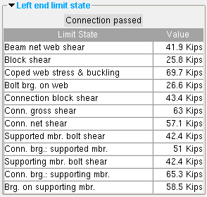
The limit states for a clip angle connection on the left end of a beam. The values shown represent the strength capacity of the connection or of the supported member (this beam) or of the supporting member. In this example, the connection passes. |
A limit state is a potential connection failure mode.
The capacity of a connection is calculated for various limit states during connection design . Each " Value " reported in the example above represents the strength of the connection or of the beam itself or of its supporting member with respect to a particular limit state.
Since connection design takes place in a full-featured SDS2 program , but not in Site Planning, the limit states that are reported on this review-only window are static and cannot be changed.
If connection design in a full-featured program has determined that the capacity of a connection is insufficient to stand up to the "
Loads " that the beam is subjected to, the program will have failed the connection and generated a connection failure message such as:
| Beam web shear capacity failed |
The Design Calculations Report together with the Connection Calculation Cover Sheet (or the Expanded Connection Design Calculations as a stand-alone report) provide formulas and the results of calculations (or the actual calculations) that relate limit states to the design of the specific connection.
page 1 | contents | review | top
|
|
|||||||||||||||
|
|
||||||||||||||
The following custom components are distributed with SDS2 programs and may be applied to beams. You therefore can potentially find settings for them on the Beam Review window:
Safety Holes Safety Tabs Web Penetration with Stiffeners Beam Outrigger Beam Stiffeners Column Stiffener at Beam HSS Cap Plate Reduced Beam Section Flange to Flange Connection
Custom component settings are shown on this window when a custom component has been added to this beam in a full-featured SDS2 program .
Settings for custom components from outside distributors can also be reviewed on this window. However, since such custom components are not distributed with SDS2 programs, they are not documented in this help manual.
Tip: An alternative to reviewing a custom component on this window is to double-click material generated by that custom component in the model. The program will open a custom component review window that includes all the settings for that custom component, but does not include the other settings that can be found on the Beam Review window.
page 1 | contents | review | top
"Properties" opens the Edit Properties window, on which you can make entries to custom properties . If, at the time it was created, your current Job was set to use a legacy flavor, the window that opens is named Custom Properties , not Edit Properties .
The Edit Properties window can also be used to read "
Log " entries or review or type "
Notes ."
Tip: Model > Member > Properties is an alternative to this button. It opens the Edit Properties window directly, without your first having to open a member review window.
" Status " opens the Member Status Review window for the beam(s) that you are reviewing. You can use that window to update status information about the beam(s).
"OK" (or the Enter key) closes the Beam Review window (this window) and saves to the member file(s) any changes made on the Member Status Review window.
Change all: If you double-clicked a beam and made a change to its status and the 3D model contains other members with the same piecemark as this member, a yes-no dialog opens after you press " OK ." On that yes-no dialog is the question, " Do you want to change all .... " Press the " Yes " button to update the status of all the beams with this piecemark; press the " No " button to change only this one beam.
Tip: The yes-no "change all" dialog tells you the count of the members with this " Piecemark ." Another way to find out the count of members under the piecemark is to look under the "
Summary " on this window.
" Cancel " (or the Esc key) closes this window without saving any status changes made on the Member Status Review window.
" Reset " undoes all status changes you made to this member on the Member Status Review window.
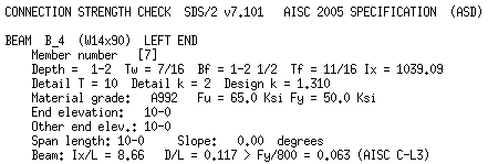
"Design Calc" outputs a report that includes this beam's connection design calculations, general settings and left/right end settings. If you are reviewing multiple beams with the same piecemark (or with different piecemarks), you get a report for each beam. Each report is output to the destination specified at User and Site Options > Output > " Reports ."
|
|
design calculations |
Tip: To get a report listing similar specifications for multiple members, output a Check Report and a Design Calculations Report .
"Expanded Calc" outputs the Expanded Connection Design Calculations report. First a PDF of the report is output to a destination of your choice. For example, to your desktop. Then the report is automatically shown in your help browser so that you can review it without manually opening the PDF file.
Expanded Connection Design Calculations is a report that provides all of the information in the Connection Design Calculations combined with related information from the Connection Calculation Cover Sheet . In addition, the report shows you the calculations written out, in detail, in the report itself, instead of simply reporting the results. Certain browser requirements must be met in order for you to access this report.
If you are editing multiple beams with the same piecemark (or different piecemarks), you get a report for each beam.
