The User Slot Lengths setup window
- This window defines the slot length that are applied when a ' User slot #1 ' or ' User slot #2 ' is the selected " Hole type " for any user-added or system-generated hole.
- See (on this page):
page 1 | contents | home > project settings > job > bolts, washers, and holes > | classic
To open the User Slot Lengths window :
page 1 | contents | home > project settings > job > bolts, washers, and holes > | classic | top
Tabs on this window :

|
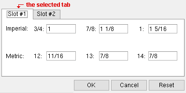
The selected tab in this example is " Slot #1 ." It applies when ' User slot #1 ' is the " Hole type ."
|
The " Slot #1 " tab applies when ' User slot #1 ' is the " Hole type ." The " Slot #2 " tab applies when ' User slot #2 ' is the " Hole type ."
|
Hole type:
|
|
User slot #1
|

|
|
|
Hole type:
|
|
User slot #2
|

|
|
|
|
page 1 | contents | home > project settings > job > bolts, washers, and holes > | classic | top
Options :
Be aware that the selection made as the primary dimension " Units " and whether or not " Lock primary units " is checked affects how the lengths are displayed.

|
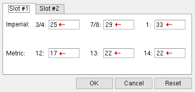
Lengths in this example are in millimeters since the primary dimension " Units " is ' Metric ' and " Lock primary units " is checked.
|
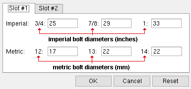
Note that each length that you enter on this window is associated with a particular bolt diameter. The standard imperial bolt diameters (in inches) are: 1/4 , 3/8 , 1/2 , 5/8 , 3/4 , 7/8 , 1 , 1 1/8 , 1 1/4 , 1 3/8 , 1 1/2 , 1 3/4 , 2 , 1 1/2 . The standard metric bolt diameters (in mm) are: 12 , 13 , 14 , ... 40 .

|
Imperial bolt diameters are in inches. Metric diameters are in millimeters. The units for lengths are the primary dimension " Units ."
|
Suppose, for example, that your " Units " are metric and the " Hole type " of a hole is ' User slot #2 ' and the selected " Bolt diameter " is 20 (mm) and, under the " Slot 2 " tab on this window you entered 50 as the length for a bolt diameter of 20 millimeters, the final result will be a " Slot length " of 50 mm.
| " Metric " slot length under the " Slot 2 " tab (this window) :
|
|
|
| Results on the Hole Edit window :
|
|
Hole type:
|
|
User slot #2
|

|
|
|
Bolt diameter:
|
|
20
|

|
|
|
|
page 1 | contents | home > project settings > job > bolts, washers, and holes > | classic | top
Applying user slots :
Users of a full-featured SDS2 program can select ' User slot #1 ' or ' User slot #2 ' as the " Hole type " for user-added holes. They can also select ' User slot #1 ' or ' User slot #2 ' for any " Hole type " that they edit.
|
Hole type:
|
|
User slot #1
|

|
|
|
Hole type:
|
|
User slot #2
|

|
|
|
|
User slots may be applied (in a full-featured SDS2 program ) during connection design based on choices to the following setup windows:
For clip angles, connection design setup windows include:
For gusset clips, the ' User slot #1 ' or ' User slot #2 ' can also be selected (in a full-featured SDS2 program ) for either leg on the following member edit windows.
Many connection design lock fields let users of a full-featured SDS2 program select ' User slot #1 ' or ' User slot #2 '.
page 1 | contents | home > project settings > job > bolts, washers, and holes > | classic | top


