All-Bolted, Single Angle ( Fabricator Settings ) (read-only)
|
Specifications for getting this type of standard clip angle in the model :
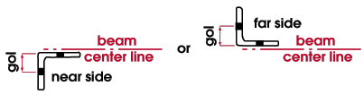
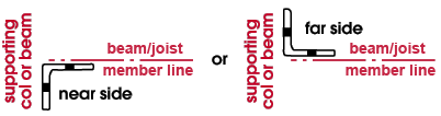
- A single all-bolted clip angle that shop bolts to the supported or supporting member is designed as the supported beam's end connection when ' Narrow Gage ' (or ' Wide Gage '), ' Bolted ' (to supported), ' Bolted ' (to supporting), ' Near Side ' (or ' Far Side ' of web) and shop attach to ' Supported ' (or ' Supporting ') are set in "
 Connection specifications " for an auto standard , user defined or beam-window-specified clip angle.
- For a web-bolted stability angle that is part of a seated beam connection, connection design (in a full-featured SDS2 program ) looks to the Single Clip Angles All-Bolted clip angle configuration. It first tries a ' Wide Gage ' angle, and then a ' Narrow Gage ' angle.
fabricator | clip configurations
![]() To open this window :
To open this window :
Method 1 : Home > Project Settings > Fabricator > Piecemarking > All Bolted Clip Angles > Single Clip Angles All-Bolted .
fabricator | clip configurations | top
| Each bolt diameter is a distinct clip angle configuration. The tabs show imperial sizes when the " Available bolt diameters " is ' Imperial '. Metric sizes are shown when the " Available bolt diameters " is ' Metric '. If " Available bolt diameters " is set to ' Both ', the primary dimensioning " Units " set whether the tabs show imperial or metric bolt sizes. |
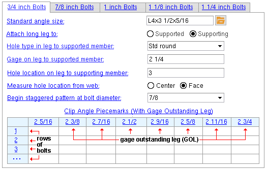
Standard angle size: The angle section size for the specific bolt diameter tab that has been selected. The angle specified here must also be listed in the local shape file .
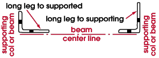
Attach long leg to: Supported or Supporting . This applies when a " Standard angle size " with unequal legs has been entered (for example, the long leg for L3 1/2x3x5/16 angle material is the leg that is 3 1 /2 inches in length).
Hole type in leg to supported member: Standard round or Short slot or Long slot or Oversized or User slot #1 or User slot #2 .

Effect on a full-featured SDS2 program: The type of hole shown here applies to the clip angle leg that attaches to the supported beam web. A full-featured SDS2 program determines the specific size of a hole based on the " Hole type . . . " shown here and the bolt diameter that is selected as the tab.
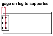
Gage on leg to supported member: The distance (in the primary dimension " Units " or in other units ) from the outside corner of the clip angle to the center of the column of holes on the leg that bolts to the supported beam.
Hole location on leg to supporting member: The distance (in the appropriate " Units ") to the center of the hole on the outstanding leg. Where this distance is measured from depends on the selection made to the " Hole location from... " field.
Measure hole location from web: Center or Face . This option sets the location that the distance set in the " Hole location... " field will be measured from.
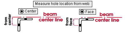
If ' Center ' is selected, the " Hole location... " is measured from the supported beam's work line . That distance minus the web thickness of the beam will determine the gage on the outstanding leg of the clip angle. Consequently, you may want to list piecemarks in more than one gage column on the " Clip Angle Piecemarks " table.
If ' Face ' is selected, the " Hole location... " is measured from the face of the supported beam's web and that distance will be the gage on the outstanding leg. You will then need to fill out only that one (1) gage column on the " Clip Angle Piecemarks " table.
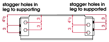
Begin staggered bolt pattern at bolt diameter: The minimum bolt diameter (in the primary dimension " Units " or in other units ) at which bolt patterns are to be staggered when a full-featured SDS2 program designs a clip angle connection.
fabricator | clip configurations | top
------ Clip angle piecemarks ------
Effect on a full-featured SDS2 program: Submaterial piecemarks shown here will be assigned in a full-featured SDS2 program to single narrowithwide gage single clip angles according the gage on the outstanding leg and number of rows of bolts designated on this table.