 Weld Combo ( Drawing Editor )
Tool summary :
Also see :
- Weld symbols character height (setup)
- Comment layer (layer type you can add a weld symbol to)
- Layer selection tool (selects layer to add to)
- Weld Input window (opened with Weld Combo )
objects > weld symbols > | objects -- weld symbols | xxx add | weld symbols
Weld Combo can be used in the Drawing Editor to add one or more weld symbols in combination with optional leader lines and pointers. The following instructions assume that you are using a 3-button mouse, that User and Site Options > General > " Point location target " is set to ' Fancy ' ( ![]() ), and that you use mouse bindings similar to those shown in these illustrations.
), and that you use mouse bindings similar to those shown in these illustrations.
Before using this tool:
(optional) : On the layer selection tool , select the comment layer that you want to add the pointer-line-weld-symbol combo to. You cannot add these objects to non-comment layers in an SDS2 review station. This step is optional because a comment layer will be created for you, if needed. Also, you can select a different layer on the Weld Input window, which opens in step 4.
(optional) : To set the to-be-added weld symbol to have the same specifications as an existing weld symbol, double-click the existing weld symbol then press " OK " on its edit window.

1 . Invoke Weld Combo . 
2 . Position the mouse pointer ( ) so the target (
) is where you want the pointer's head, then left-click ( Pointer ).

3 . Right-click ( Weld ) places the weld symbol where the target ( ) is at.

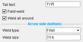
4 . On the Weld Input window, enter the settings that you want applied to the weld symbol, then press " OK ." 
5 . The weld symbol and pointer are added to the drawing. Repeat these steps to add another weld combo, or right-click ( Return ) to end the operation. Note 1: To invoke Weld Combo :
Method 1 : Click the Weld Combo icon. The icon can be taken from the group named ' Objects -- Weld Symbols ' and placed on a toolbar (classic) or the ribbon (lightning).
Method 2 : If " Drawing Editor layout style " is ' Classic ', you can use the menu system to choose Objects > Weld Symbols > Weld Combo .
Method 3, 4 or 5 : Weld Combo can also be invoked using a keyboard shortcut , the context menu , or a mode . For the ' Lightning ' layout style, configuration of the interface is done using Customize Interface .
Note 2: An arrowhead is placed at the point location target (
) the first time that you left-click ( Pointer ). Each additional left-click adds a new line segment to the leader line.

The mouse bindings that you get in step 2.

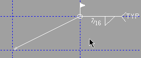
This weld symbol with a segmented leader line was created using left-click ( Pointer ) twice, middle-click ( Weld ) once.
Note 3: In step 3, doing a right-click ( Return ) instead of a middle-click ( Weld ) would end the Weld Combo operation but retain any leader lines that you already laid out, thus giving you leader lines without a weld symbol.
|
|
The mouse bindings that you get in step 3. |
|
This leader line with no weld symbol was created using left-click ( Pointer ) four times, right-click ( Return ) once. |
Note 4: Two different methods can be used to create a weld symbol with forked leader lines.
|
A weld symbol with forked leader lines. |
|
|
Hold down the Shift key to get a New Head mouse binding. |
Method 1 : If all you want is two pointer heads, then after closing the Weld Input window ( step 4 ), you can add a second leader line to the weld symbol, then right-click ( Return ).
Method 2 : You can add a second leader line before opening the Weld Input window by holding down the Shift key to get a New Head mouse binding. Left-click ( New Head ) designates that the point of the arrowhead be placed at the location of the target (
).
Note 5: Weld Combo automatically sets a weld's " Symbol rotation " to ' 0 '° when the weld symbol attaches to a pointer that points to the left. It sets the rotation to ' 180 '° when the pointer points to the right.

The left symbol is rotated ' 0 '°, and the right symbol is rotated ' 180 '°. Tip 1: When you are done, you can remove each of the weld combos you have added (one at a time) using Undo .
Tip 2: As shown here , you can drag a weld symbol to move the symbol and stretch the pointer that is attached to it. To detach the pointer from the symbol, hold down the Shift key and drag the symbol.
Tip 3: Hold down the Shift key and drag the middle of a pointer to change its curvature .
objects > weld symbols > | objects -- weld symbols | xxx add | weld symbols | top

