Construction Ellipse Edit window
- General Overview
- Related Tools
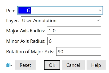
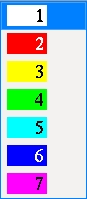
Pen color: White or Red or Yellow or Green or Cyan or Blue or Magenta. Select the display color you want to apply to the construction ellipse.
Layer: The drawing layer the construction ellipse is drawn on.
Major axis radius: The distance from the center of the construction ellipse to either one of the two points where its major axis terminates at the perimeter of the construction ellipse.
Minor axis radius: The distance from the center of the ellipse to either one of the two points where its minor axis terminates at the perimeter of the construction ellipse.
Rotation of major axis: A positive or negative number of degrees (90 to -89.9999). This controls the rotation of the construction ellipse around its Z axis, which runs through the center of the ellipse, perpendicular to the plane of your current drawing.
0 degrees makes the major axis of the construction ellipse horizontal.
A positive number rotates the construction ellipse counterclockwise.
A negative number rotates the construction ellipse clockwise.


|
|
OK (or the Enter key) closes this screen and applies the settings.
Cancel (or the Esc key) closes this screen without saving any changes.
Reset undoes all changes made to this screen since you first opened it. The screen remains open.

