Widgets and Graphics on Windows
| Active Layer | Selection dialogs: Show unavailable sizes |
| Browse and file buttons | Selection dialogs: Clear & Select All |
| Check box | Selection dialogs: Destination |
| Connection changed message | Selection dialogs: Find |
| Connection design locks | Selection dialogs: Hide & Show All |
| Copy, Paste, Save, Load buttons | Selection dialogs: Print |
| Grayed out fields (disabled or mixed) | Selection dialogs: Save & Load (selection files) |
| Job repository menu | Selection dialogs, Selecting items |
| Leaf | Selection dialogs: Status Display |
| Line type selections (printing and display) | Selection dialogs: Sub-Members |
| Member end connection failure messages | Selection dialogs: Show (erection view types) |
| Pen selections (for printing) | Selection dialogs: Show for detailing |
| Progress bar | Selection dialogs: Use as default |
| Radio buttons | Selection dialogs: Show site planning |
| Scroll bars | Selection files |
| Submaterial mark index numbers | |
| Text insertion bar (cursor) |
Browse button and File Cabinet Browse button
|
|
or |
|
- The Browse... button lets you browse your entire network for a file. For example:
- The file cabinet browse button (
 ) can be used to:
- A special case:
- The button next to Intermediate tread schedule and Top tread schedule and Bottom tread schedule on the Stair Edit window can be used to create new tread definitions that are not stored in Home > Project Settings > Fabricator > Stair Treads, but are instead stored with the stair.
- The
A check box (any Modeling or Drawing Editor edit window)
- A check box has basically two distinct settings. It can be
 checked or
  not checked.
- A check box is filled with a black square
 to indicate mixed entries.
- When a check box for a particular option is checked, then that particular option is selected. In the above example, Sequence and Member type are selected.
- Many check boxes can be checked at a time.
- Check boxes typically operate independently of one another. Checking one check box in a group will typically not affect the checked-or-not-checked state of the other check boxes in the group. You can find situations, however, where a check box serves as a master control for other check boxes, enabling or disabling those check boxes.
- For more information, see making entries to windows in SDS2.
Connection changed messages (some member edit windows in Modeling)
- A connection changed message can appear on the edit window of any member with a SDS2 connection designed connection. Specifically, such a message can appear on a Beam Edit, Column Edit, Vertical Brace Edit, Horizontal Brace Edit or Joist Edit window. Such a message can appear on either or both the left- or right-end Information leaf on that window.
| Conn changed. Possibly: Angle vs Plate |
|
# Selects all members whose design has changed, either end.
|
|
# Selects beams with end plates changed: wide to narrow gage.
|
- Also see:
Search for Connections Changed by System (a Search option)
Search > Connections changed by system (Status Display)
Connection design locks (members in Modeling)
|
The connection design locks in this example are in leaves named NS Clip and FS Clip and Beam Web Doubler. |
What are connection design locks? They are lockable fields that allow users to modify connection design parameters. They appear on edit windows for members. You can also find connection design locks when you create a user defined connection in setup and on Connection Component Edit windows for member end connections. Since member End preparations are lockable fields, they should also be considered to be connection design locks. Connection design locks are grouped under leaves with various names.
To change a setting, first set it to
locked. When you make your change to a connection design lock field, you trigger connection design to re-design the connection. Related settings that are
unlocked will be updated, and the
Left/Right end limit state calculations will be updated. Settings that are
Links to connection design lock documentation:
More links (by connection type):
- Auto base/cap plate
- Beam splice
- Bent plate
- Clip angle
- End plate
- HBrc plates
- Joist connections
- Seated beam connection
- Shear
- User base/cap plate
- User defined connections
- VBrc plates
Connection design locks cannot be changed when the Connection is set to graphical on that member's Beam Edit, Column Edit, Vertical Brace Edit, or Horizontal Brace Edit window.

Search Options, Change Options, and Status Display:
- Edit > Search > Connection design locks set
- Connection Design Lock Summary (Design Calculations)
- Search > Connection design locks set (Status Display)
- Edit > Change Options > Unlock Connection Design Locks
Lock All and Unlock All buttons at the top of the Left end settings or Right end settings sections on member edit windows can be used to
lock or
unlock all connection design locks within those sections.
Button Location Lock all Beam Edit window Lock all Column Edit window Lock all Horizontal Brace Edit window Lock all Vertical Brace Edit window Lock all Joist Edit window
 Copy, Paste, Save, Load buttons (form buttons)
|
Shown here is a partial representation of the Weld Input window in the Drawing Editor. |
General rules:
The buttons:
The Copy button. Press this button to copy to the clipboard all settings in the section (or window) that this button appears at the top of. If a field is grayed out due to mixed entries, Copy treats that field as having no entry.
The Paste button. Press this button to paste the contents of the clipboard to the section (or window) that this button appears at the top of. A paste only takes place if the settings recorded on the clipboard fit perfectly into the section. If the contents of a field are grayed out due to mixed entries, a single entry will be pasted to that field.
The Save button. Press this button to copy to a form file all settings in the section (or window) that this button appears at the top of. If the contents of a field are grayed out due to mixed entries, Save treats that field as having no entry.
The Load button. Press this button to load any form that has been saved. The contents of that form will overwrite all settings in the section (or window) that this button appears at the top of only if the form was originally saved from an equivalent section. If the contents of a field are grayed out due to mixed entries, a single entry will be entered to that field.
Tip: Right-click a Load button to get a list of recently created forms that can be applied to the section which that Load button governs. Selecting the name of a form from the list populates the fields in that section with the form settings that were saved under that name.
Grayed out fields
In the following example, fields are identified as being disabled (
), having mixed entries (
), or enabled (
). Be aware that fields with mixed entries are also enabled, though they are not marked as such in this example.
When a field is disabled (
When a field has mixed entries (
text-entry field or menu are covered with a grey block to indicate mixed entries. A check box is filled with a black square
When a field is enabled (
When mixed fields include disabled entries, those fields are disabled. For example, if you
Also see: To edit multiple objects (Drawing Editor). To edit multiple members (Modeling). You can also edit multiple materials, multiple bolts, multiple holes, or multiple welds in Modeling.
Job repository menu
A Job repository menu is available whenever you have the option to select a Job. It lets you select the file folder (repository) from which you can select the Job.
|
|
|
folder for storing jobs |
Active Layer
This displays the Active Layer, which is the layer that is currently selected on the Layer Panel. When you add new objects to a drawing, they are added to the Active Layer.
Leaf
A leaf is a collapsible section of a member edit window, a Connection Component Edit window, or of windows for custom components. Leaves hold user-editable settings and read-only information. In this documentation, the term "section" is often used to refer to a leaf.
A collapsed leaf:

An expanded leaf:
To expand a collapsed leaf, simply click on the
right-pointing triangle or its associated label. The triangle will change to a
To collapse an open leaf, simply click on the
You can also collapse and expand leaves by using the navigation tree, which can be found in the left panel on the Beam Edit, Column Edit, Vertical Brace Edit, Horizontal Brace Edit windows, as well as other member edit and connection component windows.
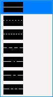
Line type selections (Drawing Editor)
Member end connection failure messages
| Beam web shear capacity failed |
Some basics:
Click any of the following links for a complete listing of the end connection failure messages that can be generated for that type of member:
Why connections fail:
Advanced Selection: The following script selects all members with failed connections on either end. It works like the Failed Connections search option.
#Selects members with failed connections on either end:
any (m.Ends).ConnectionHasFailed == TrueParametric module: ConnectionFailError
Status Display: Search > Failed connection
Search: Search for members with failed connections
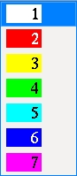
Pen selections (Drawing Editor)
Progress bar
A progress bar appears during operations such as Process and Create Solids, Detail Members, Detail Submaterial, Detail Member Groups, and Verify and Fix.
- A progress bar window is employed during automated operations that involve the opening and closing of numerous files in your current Job.
- While the progress bar is active, you should not make any changes within your current Job that might interfere with the changes that SDS2 is performing automatically.
- For most operations done in multi-user environments, potential conflicts are prevented by simply not opening files that are currently in use. For example, Process and Create Solids will not act on a member whose edit window is open, and Detail Members will not detail a drawing that is currently in use.
- When the operation is done, the progress bar window will close automatically if the box is checked ( ) for Close when done. If the window does not close automatically, you can close it by checking that same box or by pressing the OK button. You can then proceed to work within your current Job.
Radio buttons
|
Usually radio buttons are circles that are either filled or not filled with a black dot. |
Scroll bars
Scroll bars appear on certain selection dialogs, information windows and entry windows. They let you scroll up or down, thus bringing additional information into view. To scroll, drag the bar, or click an arrow head, or click a blank area you want the bar to move to.
Tip: Your mouse wheel is an excellent alternative to scroll bars, if you mouse is so equipped.
Selection dialogs: Clear & Select All
|
Clear and Select All buttons can be found on almost any selection dialog that allows selection of multiple items. |
Clear is useful when User and Site Options > General >
Select All does the same thing as using the Ctrl + a keyboard shortcut. It selects all items in the list.
Selection dialogs: Destination
|
|
The Destination is Screen |
The Screen button shown in this example may read Directory or File or Printer or Project depending on the choice made under User and Site Options > Output > Output configurations. Directory indicates output to a file folder. Dump is output to the screen only. Screen is output to the report viewer. Project is output to the Project defined output location that is specified in Home > Project Settings > Fabricator > Project Output. Pressing the button opens the Output Configuration Setup window, on which you can do either of the following:
Alternative 1: Changing Send output to on the Output Configuration Setup window temporarily overrides the output configuration settings. It does not permanently modify the output configuration that is used for the operation being performed. That output configuration is set for various operations at User and Site Options > Output > Output configurations > Reports or CNC or Drawing Conversion or etc.
Alternative 2: Pressing
Selection dialogs: Find
|
A Find entry field, a Match case check box and a Next Match button can be found on selection dialogs on which a great number of items are likely to be displayed. |
To find an item:
Selection dialogs: Hide... & Show All
|
Hide and Show All are especially useful for selection dialogs that list members. The Hide Items window features numerous options that apply to members. |
Selection dialogs: Print
|
Selection dialogs: Save & Load (selection files)
|
You can Load selection files that list materials as well as files that list members. Items listed in the file that cannot make a selection on that dialog will be ignored. |
To save a selection that has been made on a dialog, just press the Save button. You will be prompted to enter a selection file name.
To load a saved selection, press the Load button and select a selection file name. When that file is loaded, the selections saved into it will be added to your current selection. For this reason, you may want to Clear your selection first, then Load.
Selections are appropriate to the type of dialog. On a member selection dialog, you can Save selections of members into a selection file. On a material selection dialog, the selections that you Save are material selections. When you Load a selection file, any material selections that might be in that file will be ignored if you are on a member selection dialog.
Member piecemarks and member numbers: On selection dialogs such as the one for Home > Utilities > Member Edit, you have the option to select
by Piecemark or
Applications: Save and Load can be used across different dialogs; in the case of members, for example, to save and load selection files of members for updating of status or editing or report output or detailing or any other operations that can be performed on members. You can also Save to keep track of which items have been operated on using whatever operation that dialog is for.
Selection dialogs: Selecting items
Selecting items on selection dialogs follows Microsoft standards when User and Site Options > General > ![]() Classic selection lists is off (not checked). You can also Save and Load selections.
Classic selection lists is off (not checked). You can also Save and Load selections.
|
Click an item to select that item and deselect all other items. |
|
Drag or hold down the Shift key to select multiple items that are next to each other. |
|
Hold down the Ctrl key to select multiple items that are not next to each other. |
|
Double-click one item to both select that item and close the dialog. |
| Ctrl + a can be used to select all items on a selection dialog that allows multiple items to be selected. |
Selection dialogs: Show unavailable sizes
|
|
- On selection dialogs with lists for selecting section sizes, you can check the box for Show unavailable sizes if you want both available and unavailable sizes to be shown. Uncheck ( ) the box if you want only available sizes to be shown.
Selection dialogs: Status Display
|
|
- When Status Display is checked, you can press the file cabinet browse button and select a status display fie. Items listed on the selection dialog will then be color coded or masked based on the display logic in that file.
Selection dialogs: Sub-Members
|
|
- This applies to selection dialogs for Detail Sheet Autoload, Material Summary by Detail, and Detail Members.
- When Sub-Members is checked, the selection dialog lists the submembers of group members. That way you can select those submembers so that you can, for example, detail them.
Selection dialogs: Show (erection view types)
- Modeling's Select One Erection View dialog opens when you Open View. The dialog may also open when you click Modeling icon at Home. Checkboxes for Primary etc. can be found on that dialog.
|
Primary, Secondary, Dimension only, and Placement only are filter options on selection dialogs for selecting erection views. Only the erection views types that are checked will be listed. |
- When Primary, Secondary, etc., are checked, the selection dialog lists those erection view types.
- When Primary, Secondary, etc., are not checked, the selection dialog does not list those erection view types.
- An Erection view type of Primary or Secondary or etc. can be assigned to an erection view at the time that it is created in Modeling. At the time that the erection view is auto detailed, a view that is other than Placement only can optionally be dimensioned as illustrated in the diagram below:
|
Primary dimensions appear above Secondary dimensions. Dimension only erection views are auto dimensioned, but not with grid markers. Placement only grid lines cannot be auto dimensioned (Annotate erection views). |
Selection dialogs: Show for detailing
|
|
- This filter option is available on the Select One Erection View dialog that opens in Modeling when you Open View. Home > click the Modeling icon can also open the selection dialog.
- When Show for detailing is checked ( ), the selection dialog lists only erection views that are designated For detailing.
- When Show for detailing is not checked ( ), the selection dialog lists only erection views that are not designated For detailing.
Selection dialogs: Show site planning
|
|
- Show site planning can be used on the Select One Erection View dialog when, in Modeling, you Open View. Home > click the Modeling icon can also open the selection dialog.
- Show site planning can also be used on the Select Erection View dialog that opens when you Detail Erection Views.
- When Show site planning is checked ( ), the selection dialog lists only erection views that were created using SDS2 Basic. Such erection views are usually created to depict crane placements.
Selection dialogs: Use as default & Clear Default
|
The Clear Default button clears the default. |
To set a Modeling erection view to be your default, do the following:
1. Open the erection view selection dialog. To do this, you can Home > click the Modeling icon. If you are already in Modeling, you can Open View.
2. Select an erection view and check the box for
3. The next time you Home > click the Modeling icon, the default erection view that you selected in step 2 will open directly, without the intervening erection view selection dialog.
To clear the default that you set for yourself:
1. In Modeling, Open View.
2. Press the Clear Default button.
3. The next time you Home > click the Modeling icon, the erection view selection dialog will open.
Please note: The default erection view is stored per user per Job. This means that if you are working in a multi-user environment, no other users in that Project will be affected when you select an erection view to be your default.
Also in Modeling, when you create a grid line, you have the option to
Selection files
|
A list of selection files is displayed when you press Load on a dialog, or when you Edit > Load Selection or when you Edit > Edit Selection in Modeling. |
| Entries in a Selection File (click here for related Modeling help) |
|
| Entry | Resulting Selection in a Dialog |
| [94] |
On a multi-member selection dialog where |
| [94] B_77 |
On a dialog where |
| B_77 |
On a dialog where |
| a1 | On a submaterial-selection dialog, a1 selects all submaterials under the submaterial mark a1. |
| GM_83 |
Where |
| Exceptions:Of course, if you use unusual naming schemes for piecemarking -- for example, give members and submaterials the same marks -- then submaterial marks maintained in the selection file could select members or member marks could select submaterials. The examples above are based on a common naming scheme employed by SDS2. | |
A selection file stores selections of members or materials on dialogs, or of members or materials in the model. A selection file is, by default, stored in your current Job, in the
lists folder. You can, however, store a selection file at another location. If selection files are stored in the lists folder, any user of your current Job can access them.
Creating a selection file in a dialog: In Modeling or the Drawing Editor or anywhere else that you can open a selection dialog that allows selection of multiple members, select some items (members or materials) on that dialog, then press the Save button. You will be prompted to give the selection file a name.
Creating a selection file in the model: In Modeling, select some members, then choose Edit > Save Selection..., then give the file a name.
Creating a selection file from another selection file: In Modeling, choose Edit > Edit Selection. Make the desired changes, then press the Save As button and give the new file a name.
Loading a selection on a dialog: Save and Load buttons can be found on dialogs for selecting multiple members, or on dialogs for selecting multiple submaterials. To load a selection file, press that dialog's Load button. Members that are referenced in the selection file will be automatically selected on that dialog.
Loading a selection in the model: In Modeling, choose Edit > Load Selection. Select the selection file that you want. The items in that file will be selected in the model. Note that a selection file for materials selects all materials under each submaterial mark that is referenced in that file.
Submaterial mark index numbers
Submaterial mark index numbers are assigned to materials to help you determine which materials with the same submaterial mark have the same settings on their edit windows. You can find these index numbers on the Model Tree, when selecting submaterials on the context menu, or in the balloon description that appears when you hover a submaterial with your mouse pointer ( ![]() ).
).
|
In this screen shot of the Model Tree, the a58 materials with the index number #215 have In set as their Toe direction. The submaterials with the index number #216 have Out set as their Toe direction. |
Basic principle for index number assignment: Some material edit window settings can shift or rotate the material in the model. For example, a rectangular plate's Thickness reference point can be changed from NS to FS, or a channel's Toe direction can be switched from In to Out. These settings do not cause that material to be assigned a different submaterial mark. They do, however, directly influence the index number that is assigned to a material. Left/right end settings also influence the index number. Material's with the same index number have the same material edit window settings.
| Some (not all) settings that may cause submaterials with the same marks to have different index numbers | |
| most materials | left/right end settings that are equivalent but on opposite ends. |
| any rolled section | Centered |
| angle or channel | Toe direction |
| angle | Long leg |
| rectangular plate | Thickness reference point |
| round plate | Thickness reference point |
| bent plate | Centered |
| rolled plate | Centered |
| round bar | Centered |
| round bar | Depth reference point |
Cuts and holes may also generate different submaterial mark index numbers. In the following example, the placement of holes results in different index numbers on three of the four rectangular plates. The hole in each P47#301 is on the right, bottom end of the plate. On the P47 #302, the hole is on the left, bottom end. To superimpose P47 #302 on P47 #301, you could flip it, or you could rotate it 90 degrees.
Materials with cut layouts, copes or clips or hole patterns that can be superimposed on one another are assigned the same submaterial mark. This is true even if the holes or cuts are on different ends (top or bottom; left or right) of the materials. If a material needs to be flipped or rotated in order to superimpose its hole pattern or cut layout on another material, the two materials will have different index numbers.
They will also have the same index numbers if those hole patterns or cuts can be superimposed on one another without your having to rotate or flip the material.
The following is an example of four plates with the same submaterial mark. Some of the plates have different index numbers because the corner clip operations on them were entered using equivalent settings at different left/right and/or top/bottom locations on the Rectangular Plate Material window.
If you were to edit one of the two p4 #101 plates illustrated above and, for example, change its steel grade, you would get the Change all options shown below. The Change all identical material option reads 2 because there are only two #101 plates.
The Change all identical material option which you get when you edit a single material will only apply changes to materials with the same index number when the Change all method is
If you multi-edit materials with the same submaterial mark but different index numbers, certain fields may have mixed entries on the edit window. If you change the mixed entries to a single entry, some of the edited materials may shift to a new location in the model, or cuts may move to the opposite end of the material.
Members that are composed of the same submaterials will be assigned different member piecemarks if the index numbers of those submaterials are different.
Text insertion bar (cursor)
- When this cursor (
 ) appears in a field, the user can type in text. The new text is inserted at the position of the insertion bar. A double-click selects all text that is entered to the field.
- The initial behavior of a text entry field depends on the selection made to User and Site Options > General > When an entry field is clicked.
- A number of text entry widgets exist for text insertion.

