The Ellipse Setup window ( Drawing Editor )

In versions of SDS2 software prior to v2018, you could rotate circles to make them into ellipses . Now circles and ellipses have different edit windows. The circle edit window is called Circle Setup . For multi-edit operations consisting of both circles and ellipses, this window -- Ellipse Setup -- is the window that opens.

Also see :

page 1 | contents | objects > circles > | objects -- circles | top


" Copy " " Paste " " Save " " Load " buttons :

  • You'll find buttons like these at the top of this window. They apply to all user-editable settings that are on this window. Click here for more information.
  • You can " Copy " ( ) the settings on this window, then change the " Circle__of " number you are editing using the VCR buttons, then " Paste " ( ) those settings to the newly selected circle or ellipse.
  • " Save " ( ) saves a "form" file to the form/circle folder that is used by your current version of this program. Give the form a name that will help users in other Jobs on your network identify its purpose. " Load " ( ) changes all settings on this window to those settings that are stored in the file that you select.
  • " Paste " and " Load " replace mixed entries to a single field with a single entry. " Copy " and " Save " ignore fields with mixed entries, treating them as if they have no entry or do not exist.

page 1 | contents | objects > circles > | objects -- circles | top


------ Settings ------

Major axis radius: The distance (in the primary dimension " Units " or other units ) from the center of the ellipse to either one of the two points where its major axis terminates at the perimeter of the ellipse.


The major axis of an ellipse is the axis that terminates at the two points that are farthest from one another on the perimeter of the ellipse. In other words, it is the ellipse's largest diameter. The " Major axis radius " is the length of half of the major axis.

When circles and ellipses are multi-edited, a change made to the " Major axis radius " changes the radius of circles.

Minor axis radius: The distance (in the primary dimension " Units " or other units ) from the center of the ellipse to either one of the two points where its minor axis terminates at the perimeter of the ellipse.


The minor axis of an ellipse is perpendicular to the ellipse's major axis and runs through the center of the ellipse.

Rotation of major axis: A positive or negative number ( 90 to -89.9999 ) of degrees. This controls the rotation of the ellipse around its Z axis, which runs through the center of the ellipse, perpendicular to the plane of your current drawing.


' 0 ' degrees makes the major axis of the ellipse horizontal.

A positive number rotates the ellipse counterclockwise.

A negative number rotates the ellipse clockwise.

Line type: No button is pressed if you are editing multiple circles and/or ellipses that have different dash patterns.

The button that is pressed sets the line type (dash pattern) of the circle(s) you are editing.

Pen color: 1 or 2 or 3 or 4 or 5 or 6 or 7 . No button is pressed if you are editing multiple circles and/or ellipses that have different colors.

The button that is pressed sets the printing pen number (and on-screen display color) of the ellipse.
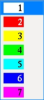
 Line Weights sets the printed thickness for each of the seven pen numbers.
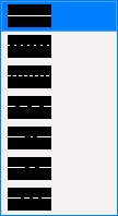
Attached to view: A number designating the view that this ellipse is attached to. This applies mainly to member details . For instance, a column detail may have a view of face A, face B and face C. It may also have various section views (Section A-A, Section B-B, Section C-C). All graphical objects that are in a particular view are assigned the same number. The only other type of drawing on which you might find multiple views is a submaterial detail .

Assigning the correct number to an object (line, weld symbol, label, etc.), prevents Shorten and Unshorten problems on submaterial details and member details . Automatically detailed submaterial details and member details are the two Drawing Editor drawing types that can have multiple views.


To show a view's number, you can add the X-Y-Z Display to your toolbar. An alternative decoration you can add to display view numbers is the X-Y Dual Show/True Display .

In the Drawing Editor , the X-Y-Z Display shows the view number that the point location target ( ) is over.

Troubleshooting: If you Unshorten a drawing then Shorten , only to find that objects are repositioned in a way that seems wrong, the problem might be that the objects are attached to a view that is not the view that they should be attached to. A good troubleshooting method is to select all of the objects that you believe should be attached to the same view, then right-click ( Menu ) and choose " Edit " on the menu . This will open the Multi-Items Edit window. Look at the " Attached to view " field on that window. If that field is gray (shows no view number), then that field has a mixed entry , indicating that objects in your selection have have two or more different view numbers. Entering the desired view number to the " Attached to view " multi-edit field assigns all objects in your selection that one view number.

View number assignment is fairly random. While view numbers assigned during auto detailing are generally the same as the numbers assigned to views in member isolation (or material isolation's edit views mode ), there are cases where that general one-to-one correspondence will not hold. Also, while the main view of a member detail is almost always view 0, the other views are assigned numbers as they are added, and since the order in which views are added is arbitrary, there is little correspondence between a view's number and its type.

How can objects be assigned wrong view numbers? When a user adds an object to a drawing on which there are multiple views (a member detail or a submaterial detail), it is the responsibility of that user to ensure that the object is attached to the correct view. That sounds like an easy thing to do, but it isn't always so simple. Take, for example, a pointer . When a user adds a pointer using Objects > Pointers > Add , the user does not see the Pointer Edit window and therefore does not see the " Attached to view " entry field. Pointers can also be added using Paste , Paste at Original Location , Paste Repeatedly , Paste Special , Paste to Several , Add Standard Detail , Add Standard Detail to Several , Add Weld Combo , Hole Sym Combo , Label Combo , etc. Each of these tools is a different way for users to add a pointer to a wrong view.

Layer: The drawing layer (any layer given a " Name ") that the ellipse you are adding or editing will be drawn on after you press " OK " to close this window. If that layer happens to be hidden (not marked " Show "), the ellipse will disappear after the first Redraw .

Defaults: For an add operation, the default selection ( ) made here is the layer that was selected on the layer selection tool before you began the operation. For an edit operation, the default selection is the layer that the ellipse is currently on.

Fill: or .

The blue circles in this example are on a "higher" drawing layer than are the yellow circles. The higher layer is also the higher layer on the list box menu for " Layer " (above).

If this box is checked ( ), the ellipse or circle is filled, thus making it opaque. Notice in the example shown above that opaque drawing objects overlap based on the drawing layer that they are on. The " Move Up " and " Move Down " buttons on the Edit Layers window can be used to change the drawing order of layers.

If the box is not checked ( ), the ellipse or circle is not filled.

page 1 | contents | objects > circles > | objects -- circles | top


For when you edit one ellipse and multiple circles are in the drawing :

Circle _ of __ (not applicable to Add Circle or multi-edit) : The number of the one circle or ellipse you are editing and the total count of circles (including ellipses) in your current drawing. You can use the VCR buttons to select a different circle or ellipse and edit that object's settings while still on this window. When a circle or ellipse on a shown layer is selected, it is displayed in green (cyan if its actual color is green). The selected circle or ellipse must be on a shown layer for it to be shown.

VCR buttons (first-previous-next-last) for selecting a circle or ellipse to edit.

Note: If you change one circle or ellipse, then select a different circle number, the first circle or ellipse remains changed even if you press " Cancel " on this window.

page 1 | contents | objects > circles > | objects -- circles | top


To close the Ellipse Setup window :


"OK" (or the Enter key) closes this window and applies the changes made on it to your current drawing.

Defaults: When you press " OK ," settings on this window become the default settings for the next circle or ellipse you add during this session of the Drawing Editor . Even if all you do is double-click an ellipse and press " OK " without making any changes on this window, this window's settings become the defaults for the next-added circle. To override this behavior, " Pen color " & " Line type " can be changed using the Edit Palette .

Note: After making changes to this window and pressing " OK ," you can still undo your changes by using Revert or Undo . If you Save to make your changes permanent, you can no longer Revert , but you can still Undo .

"Cancel" (or the Esc key or the button) closes this window without saving any of the changes you have made.." Cancel " only cancels the changes made to the circle or ellipse whose number is currently selected as the " Circle _ of __ ."

Defaults: The settings on this window do not become the defaults for new circles if you press " Cancel " to close this window (unless you used " Circle _ of __ ").

Tip 1: If you used " Circle _ of __ " to edit more than one circle, then Undo (after you have closed this window) does undo all those changes.

Tip 2: If you double-click an ellipse just to review it and don't want to set the defaults for to-be-added circles, the best way to close this window is to press " Cancel. "

page 1 | contents | objects > circles > | objects -- circles | top