Step 3: Constructing a 3D Model
On this page :
Also see :
- adding beams (
 )
)
- adding columns (
 )
)
- adding horizontal braces (
 )
)
- adding vertical braces (
 )
)
- adding miscellaneous members
- adding a stair
Introduction :
page 1 | contents | overview | top
Reference drawings :
page 1 | contents | overview | top
Start up Modeling :
page 1 | contents | overview | top
Before laying out members :
Create a plan view of every floor in the structure that you are modeling.
| YouTube video: Instead of Open View , you can double-click a grid line bubble to open the erection view that is associated with that grid line . (Recorded in SDS2 Detailing , v2020i) |
If you imported a reference drawing that was a plan view, you may at this time wish to add that drawing.
- Open ( Ctrl + o ) the view (created in the previous step) that is at the elevation of the reference drawing that you want to add.
- Choose Model > Reference Drawing > Reference Drawing Tools , then press the " Add " button. Place the view at the appropriate location.
Lay out construction lines for placement of grid lines:
Lay out grid lines (erection views) to provide INCL points for member work point layout in plan views.
| YouTube video: Grid lines are added in a plan view by locating points at intersections of construction lines. New Erection View options are explained . (Recorded in SDS2 Detailing , v2020i) |
| YouTube video: Instead of Open View , you can double-click a grid line bubble to open the erection view that is associated with that grid line . (Recorded in SDS2 Detailing , v2020i) |
Notice when you are laying out grid lines (erection views) that an arrowhead appears on screen.
![]()
- This arrowhead points in the direction that the view looks when you Open ( Ctrl + o ) that view.
Erection views should be laid out in a consistent way.
page 1 | contents | overview | top
Member layout is a three-step process, a four-step process for miscellaneous members:
3. Specify the member settings
4. Member rotation (optional for miscellaneous members)
page 1 | contents | overview | top
Member selection :
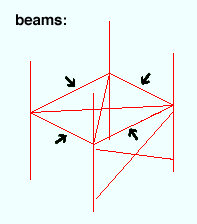
Beams are typically the most commonly used members in the model. A beam is a structural member whose primary function is to carry loads transverse to its longitudinal axis.
|
|
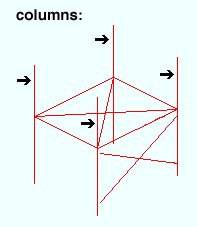
Columns are relatively long vertical or sloping member whose primary function is to carry compression loads parallel to its longitudinal axis. System connections can be designed to sloping columns as well as to columns that are perfectly vertical.
|
|
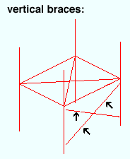
Vertical Braces are braces that slope and whose gusset plates are vertical.
|
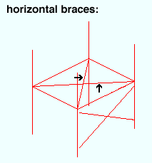
Horizontal Braces are braces that are perfectly horizontal or sloping and whose gusset plates are parallel with the flanges of the beam being framed to.
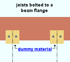
Joists can be rendered in Modeling using various " Panel display methods ."Joist are not auto detailed. It is assumed that a joists is ordered from a joist manufacturer and will not be shop fabricated. You can, however, generate a Joist Report which can serve as a bill of material for ordering joists.
Girts (legacy) and Purlins do not have any automatic connections that connection design can design for you.
- You can get connections -- but not designed connections -- using the Girt member, which is a type of custom meber.
Miscellaneous members can be made up of any type of material that you can add to a member as a submaterial. See the Material Type Selection window for a list of these materials. Shown below is decking, one of the types of material you can add to the model as a miscellaneous member.
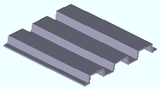
As with other member types, miscellaneous members are assigned member piecemarks . Work point layout is different for different material types. Connections are NOT automatically designed on miscellaneous members. Users need to Add Material or Add Assembly or Run Parametric to add connection materials to a miscellaneous member.
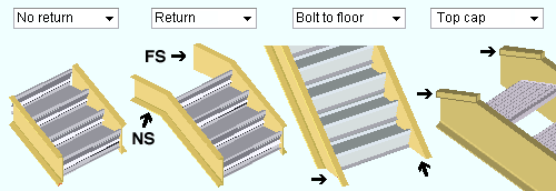
A stair can have one or two returns, no returns, or can be bolted to the floor.
Custom members that are currently provided with SDS2 programs include Hand Rail , Embed Embed Plate , Sag Rod ( ![]() ), Anchor Rod , Caged Ladder , Engineered Column , Engineered Rafter , Roof Frame (
), Anchor Rod , Caged Ladder , Engineered Column , Engineered Rafter , Roof Frame ( ![]() ) and others.
) and others.
- Since these member types are developed from parametric Python code, they are relatively easy to develop, and more types are likely to become available.
- It is also possible for users to add new custom members or to create modified copies of the custom members that come with SDS2 programs.
page 1 | contents | overview | top
Lay out members of the same type at the same time :
page 1 | contents | overview | top
Locate work points :
- Use Locators to lay out work points. By locating points in a view, you are defining the spatial geometry ( work line , end elevation, framing condition, etc.) of members within the 3D model .
Locators look like these: 


Auto INCL INCM EXPT FRPT DXDY BSCL ANGL
Or like these in the example below: 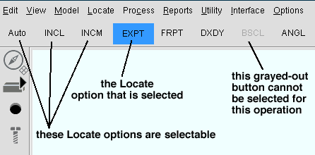
|
|
| X coordinate, Y coordinate, Z coordinate |
INCL (
) (intersection of construction lines) is the most commonly used point locator. It finds points at intersections of construction lines and/or construction circles and/or grid lines. If you lay out members in a plan view using INCL (with Offset Controls set to zero offsets), the elevation of the work points you locate is the reference elevation of the plan view. For a horizontal (non-sloping) beam, this means that its top flange is at the elevation of the plan view.
INCM (
) (intersection of a construction line and member) is an excellent choice for framing a beam to a sloping beam in a plan view. So long as Offset Controls are set to zero offsets, the work point will be at the elevation of the top flange of the sloping beam.

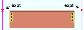
EXPT (
) (exact point) finds member work points. The exact points shown below are the work points of the beam. The columns this beam frames to are displayed in stick form. The beam's material is set back from the columns' worklines because the beam frames to column flanges.
DXDY is an excellent choice for laying out sloping members such as vertical braces or sloping beams in a plan view.
| DXDY to add a sloping beam
(instructions assume that you are using a 3-button mouse) |
|
|
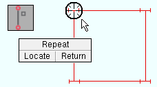
1 . Invoke Add Beam , then left-click ( Locate ) when the target ( |
|
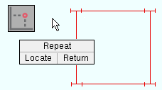
2 . The status line prompts, "Locate second point ." Select DXDY as the Locate option, then left-click ( Locate ) anywhere in the drawing area. |
|
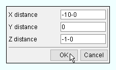
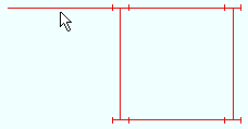
3 . In the DX/DY Offset window, enter the X, Y and Z distance from the first point to the beam's second point, then press " OK ." |
|
4 . After you enter settings and press " OK " on the Beam Edit window, the beam appears in the view. |
- Work points for a column: You can lay out a column in a plan view with a single work point, then set the top and bottom end elevations of the column on its edit window. In an elevation view , column layout requires two points. Sloping columns can be added in an elevation view.
page 1 | contents | overview | top
Specify member settings :
page 1 | contents | overview | top
After the member appears in the view :
page 1 | contents | overview | top
Also note :
Also see :
