Steel Buildings in Europe Verification Problem Example
Angle Web Cleats – Beam to Column
- Example
- Related
Problem Statement
This document presents a comparative study between the published Steel Buildings in Europe, Multi-Storey Steel Buildings, Part 5: Joint Design and the results generated by SDS2 version 2025.01 connection software for section 4.4 Worked Example – Angle Web Cleats. The central problem statement is to verify the available strength of an angle web cleat connection between a beam and supporting member. This connection involves an IPE A 550 beam. Shear reaction on the beam is 450kN with a tying force of 370kN. The beam material is Grade S275 steel. The connection uses M20 8.8 bolts and grade S275 steel for the angle web cleats. The connection detail is shown in Figure 1.
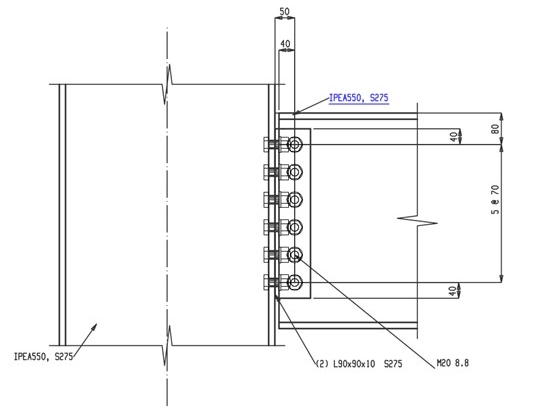
Figure 1. The 4.4 Worked Example: Angle Web Cleats
Connection design report output from SDS2 for this connection:
Note: To view the 3D model (U3D) of the structural joint in the PDF files, open the PDF using Bluebeam or Adobe Acrobat Reader.
Validation Method
The connection as shown in Steel Buildings in Europe, Multi-Storey Steel Buildings, Part 5: Joint Design, section 4.4 page 5-68, Worked Example – Angle Web Cleats (see reference 1) was modelled in SDS2 and a connection design report was generated.
The core of this report features a comparison table for each connection limit state, displaying the calculated capacities from both SDS2 and the cited document. The order of the limit state table generally mirrors the sequence in which it was presented in the Part 5: Joint Design, section 4.4 example problem. This table also highlights the percent difference (% Δ) between these calculated values, providing a clear measure of any discrepancy, if any.
To further enhance understanding, this report includes relevant notes that discuss any differences or assumptions made during the calculation process. This comparative study's goal is to evaluate the precision and efficiency of the SDS2 connection design software in contrast to the Eurocode 3 UK design example and serves as a guide for better understanding and application of these design calculations.
Comparison
A comparison of the limit state checks is presented in Table 1. The limit state checks and calculated values aligned well between the published Eurocode 3 UK design example document and the calculation generated by SDS2. The minor differences in calculated values, except where noted, were a result of rounding differences.
Other minor differences are discussed in the comparison table notes.
|
Table 1. Capacity comparison table for Eurocode 3 UK |
||||
|
Limit state on angle web cleat connection |
SDS2 Capacity |
Published Capacity |
%Δ |
Notes |
|---|---|---|---|---|
|
Web leg-bolt shear |
962.0 kN |
962.0 kN |
0.0% |
|
|
Bolts-bearing on web cover plates |
1066.8 kN |
1075.0 kN |
-0.8% |
|
|
Web leg-bearing on web |
582.5 kN |
583.0 kN |
-0.1% |
|
|
Outstanding leg-bolt shear |
94.0 kN / bolt |
94.0 kN / bolt |
0.0% |
|
|
Outstanding leg-bearing on angles |
891.1 kN |
902.4 kN |
-1.3% |
|
|
Outstanding leg-bearing on support |
891.1 kN |
902.4 kN |
-1.3% |
|
|
Shear yielding of angles |
1075.1 kN |
1076.0 kN |
-0.1% |
|
|
Shear rupture of angles |
1345.1 kN |
1184.0 kN |
12.0% |
|
|
Connection-block tearing of web legs |
967.6 kN |
954.0 kN |
1.4% |
|
|
Connection-block tearing of osl legs |
1088.7 kN |
954.0 kN |
12.4% |
|
|
Shear yielding of beam web |
957.3 kN |
953.0 kN |
0.4% |
|
|
Supporting beam-net web shear |
1092.7 kN |
956.0 kN |
1.2% |
|
|
Tying resistance-angles and bolts |
683.4 kN |
696.0 kN |
-1.8% |
|
|
Tying resistance-angles gross/net tension |
2096.8 kN |
|
|
|
|
Tying resistance-web leg bolt shear |
1281.8 kN |
1284.0 kN |
-0.2% |
|
|
Tying resistance-bolt bearing on angles |
1421.5 kN |
1428.0 kN |
-0.5% |
|
|
Tying resistance-block shear of angles |
2060.6 kN |
2060.0 kN |
0.0% |
|
|
Tying resistance-bolt bearing on beam |
639.7 kN |
642.0 kN |
-0.4% |
|
|
Tying resistance-beam web tension |
943.6 kN |
944.0 kN |
0.0% |
|
|
Tying resistance-beam web block shear |
927.2 kN |
927.0 kN |
0.0% |
|
|
Bending & prying of angles (SI) |
282.2 kN |
|
|
|
|
Shear yielding of OSL (SI) |
1075.1 kN |
|
|
|
|
Shear rupture of OSL (SI) |
1282.6 kN |
|
|
|
Table Notes
Note 1: The αb value calculated inside of SDS2 is 0.606061 and the value calculated in Part 5: Joint Design is 0.61.
Note 2: SDS2 includes the long joints affects from section 3.8 “BS EN 1993-1-8_2005” equation 3.5. Part 5: Joint Design does not include this effect.
Note 3: Part 5: Joint Design appears to use a γM2 value of 1.25 as given in Table NA.1 of UK NA to BS EN 1993-1-8:2005. SDS2 uses a γM2 value of 1.1 as given in NA.2.15 of UK NA to BS EN 1993-1-8:2005.
Note 4: When calculating the block tearing capacity of the outstanding leg, Part 5: Joint Design uses a tension term of
Vrd,b = 0.5*fu,b*Ant/ γM2 . SDS2 uses Vrd,b = fu,b*Ant/ γM2. SDS2 only includes the 0.5 factor if hp < 1.36p3 as is shown in the partial depth end plate design procedure of SCI’s Joints in Steel Construction: Simple Joints to Eurocode 3 (P358).Note 5: SDS2 calculates a cross-sectional shear area of Av=11728.8 mm2. Part 5: Joint Design uses 11700 mm2.
Note 6: SDS2 is conservatively using a value for “Width across points of the bolt head or nut, dw” of 33 mm whereas Part 5: Joint Design is using the standard washer width of 37 mm.
Note 7: SDS2 checks both a ‘C’ shaped and ‘L’ shaped tearout pattern when calculating block shear capacity. Part 5: Joint Design only checks the ‘C’ shaped pattern. The Value shown in the table for SDS2 capacity is for the ‘C’ shaped pattern. The capacity of the ‘L’ shaped pattern is more conservative.
Note 8: These limit states are not included in the design example from Part 5: Joint Design Worked Example: Angle Web Cleats.
References
- Fin Plates – Beam to Beam (left beam connection)
- Fin Plates – Beam to Beam (right beam connection)
- Fin Plates – Beam to Column Web – Tying Resistance
- Partial Depth End Plate – Beam to Beam (left beam connection)
- Partial Depth End Plate – Beam to Beam (right beam connection)
- Partial Depth End Plate – Beam to Column Web – Tying Resistance
- Full Depth End Plate – Beam to Column
- Moment End Plate

