Steel Buildings in Europe Verification Problem Example
Moment-Resisting Joints To Eurocode 3
- Example
- Related
Problem Statement
This document presents a comparative study between the published Joints in Steel Construction: Moment-Resisting Joints to Eurocode 3 and the results generated by SDS2 version 2025.01 connection software for Example C.1 – Bolted end plate connection (unstiffened). Eurocode 3 UK Annex is used in SDS2. The central problem statement is to verify the available moment strength of an extended moment end plate connection. This connection involves two 533 x 210 x 92 UKB beams and one 254 x 254 x 107 UKC column, the steel grade is S275. It is assumed that the design moments in the two beams are equal and opposite. The connection detail is shown in Figure 1.
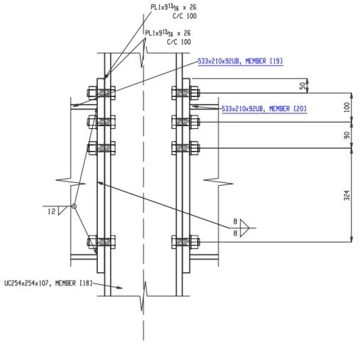
Figure 1. Example C.1 Elevation View
Connection design report output from SDS2 for this connection:
Note: To view the 3D model (U3D) of the structural joint in the PDF files, open the PDF using Bluebeam or Adobe Acrobat Reader.
Validation Method
The connection as shown in Joints in Steel Construction: Moment-Resisting Joints to Eurocode 3, Example C.1 (see reference 1) was modelled in SDS2 and a connection design report was generated.
The core of this report features four comparison tables for connection limit states, displaying the calculated capacities from both SDS2 and Eurocode 3 UK. These tables also highlight the percent difference (% Δ) between these calculated values, providing a clear measure of any discrepancy.
To further enhance understanding, this report includes relevant notes that discuss any differences or assumptions made during the calculation process. This comparative study's goal is to evaluate the precision and efficiency of the SDS2 connection design software in contrast to the Eurocode 3 UK example and serves as a guide for better understanding and application of these design calculations.
Comparison
Table 1 lists the limit states. However, only the first limit state, moment resistance, is compared, because only this resistance is calculated in Example C.1.
Since the moment resistance calculation involves multiple connection component resistance calculations, these tables are added to compare the component resistances.
Table 2 compares the effective resistances of bolt rows, column web in compression, beam flange and web in compression, and adjusted (final) resistances of bolt rows.
Table 3 is a copy of the table “Summary of tension resistances” on page 101 for Example C.1. This table summarizes the effective tension resistance for each bolt row in the tension zone, which is the minimum resistance of the following:
- Bending in the column flange.
- Tension in the column web.
- Bending in the end plate.
- Tension in the beam web.
Table 4 is the same table as Table 3 with the values calculated by SDS2.
|
Table 1. Resistance Comparison of Example C.1 |
||||
|
Limit state |
SDS2 Resistance |
Euro UK Resistance |
%Δ |
Notes |
|---|---|---|---|---|
|
End plate moment (KN*m) |
425.9 |
416.0 |
2.38% |
|
|
Connection-bolt shear (KN) |
498.1 |
N/A |
N/A |
|
|
Supported beam-web shear (KN) |
402.4 |
N/A |
N/A |
|
|
Supported beam-moment strength (KN*m) |
649.0 |
N/A |
N/A |
|
|
Connection-bearing on plate (KN) |
2668.2 |
N/A |
N/A |
|
|
Connection-bearing on support (KN) |
2187.9 |
N/A |
N/A |
|
|
Supported beam-flange welds |
N/A |
N/A |
N/A |
|
|
Supported beam-welds |
N/A |
N/A |
N/A |
|
Table 2. Comparison of Component Resistances for Moment | ||||
Component resistances for moment | SDS2 Resistance | Euro UK Resistance | %Δ | Notes |
|---|---|---|---|---|
Effective resistance of bolt row 1 (KN) | 376.9 | 377.0 | -0.03% | |
Effective resistance of bolt row 2 (KN) | 320.8 | 320.0 | 0.25% | |
Effective resistance of bolt row 3 (KN) | 292.2 | 291.0 | 0.41% | |
Column web in transverse compression (KN) | 867.0 | 841.0 | 3.09% | |
Beam flange and web in compression (KN) | 1254.1 | 1254.0 | 0.01% |
|
Adjusted resistance of bolt row 1 (KN) | 376.9 | 377.0 | -0.03% | |
Adjusted resistance of bolt row 2 (KN) | 320.7 | 320.0 | 0.22% | |
Adjusted resistance of bolt row 3 (KN) | 169.3 | 144.0 | 17.57% | |
Design moment resistance (KN*m) | 425.9 | 416.0 | 2.38% |
|
Table 3. Resistance of tension bolt rows from Example C.1 | |||||||
Resistances of rows Ftr, Rd (KN) | Column flange | Column web | End plate | Beam web | Minimum | Effective resistance | Notes |
|---|---|---|---|---|---|---|---|
Row 1, alone | 398 | 790 | 377 | N/A | 377 | 377 |
|
|
|
|
|
|
|
|
|
Row 2,alone | 398 | 790 | 406 | 675 | 398 |
|
|
Row 2, with row 1 | 697 | 1126 | N/A | N/A | 697 |
|
|
Row 2 |
|
|
|
| 320 | 320 |
|
|
|
|
|
|
|
|
|
Row 3, alone | 398 | 790 | 406 | 675 | 309 |
| |
Row 3, with row 1 & 2 | 988 | 1431 | N/A | N/A | 988 |
|
|
Row 3 |
|
|
|
| 291 | 291 |
|
Row 3, with row 2 | 691 | 1096 | 812 | 1052 | 691 |
|
|
Row 3 |
|
|
|
| 371 |
|
|
Table 4. Resistance of tension bolt rows from SDS2 | |||||||
Resistances of rows Ftr, Rd (KN) | Column flange | Column web | End plate | Beam web | Minimum | Effective resistance | Notes |
|---|---|---|---|---|---|---|---|
Row 1, alone | 398 | 790.4 | 376.9 | N/A | 376.9 | 376.9 |
|
|
|
|
|
|
|
|
|
Row 2,alone | 398 | 790.4 | 406.1 | 672.8 | 398 |
|
|
Row 2, with row 1 | 697.7 | 1129.6 | N/A | N/A | 697.7 |
|
|
Row 2 |
|
|
|
| 320.8 | 320.8 |
|
|
|
|
|
|
|
|
|
Row 3, alone | 398 | 790.4 | 406.1 | 672.8 | 398 |
| |
Row 3, with row 1 & 2 | 989.9 | 1434.8 | N/A | N/A | 989.9 |
|
|
Row 3 |
|
|
|
| 292.2 | 292.2 |
|
Row 3, with row 2 | 690.3 | 1095.6 | 807.6 | 1036.7 | 690.3 |
|
|
Row 3 |
|
|
|
| 369.5 |
|
|
Table Notes
Note 1: SDS2 uses full strength welds in Moment end plate for Eurocode 3 UK national annex. SDS2 checks the sizes of flange weld and web weld to verify if they are full strength welds in the design report.
Note 2: See detailed comparison in Table 3 and Table 4.
Note 3: Example C.1 contains an error. The published example uses 8 mm as the flange weld size. This should be 12 mm.
Note 4: This bolt row resistance in Example C.1 is smaller because only this bolt row is adjusted by the column web resistance which is smaller than in SDS2.
Note 5: This is the bolt row tension resistance adjusted with the column web compression, beam flange and web compression and the plastic distribution limit.
Note 6: It is suspected the number “309” in Example C.1 is a typo and should be 398 (the minimum of 398, 790, 406 and 675).
References
- Angle Web Cleats – Beam to Column
- Fin Plates – Beam to Beam (left beam connection)
- Fin Plates – Beam to Beam (right beam connection)
- Fin Plates – Beam to Column Web – Tying Resistance
- Partial Depth End Plate – Beam to Beam (left beam connection)
- Partial Depth End Plate – Beam to Beam (right beam connection)
- Partial Depth End Plate – Beam to Column Web – Tying Resistance
- Full Depth End Plate – Beam to Column

