Steel Buildings in Europe Verification Problem Example
Partial Depth End Plate – Beam to Beam Right Beam Connection
- Example
- Related
Problem Statement
This document presents a comparative study between the published Joints in Steel Construction: Simple Joints to Eurocode 3 and the results generated by SDS2 version 2025.01 connection software for the right beam connection of Example 1 – Partial depth end plate – Beam to beam. The central problem statement is to verify the available strength of an end plate connection between a beam and a supporting beam web. This connection involves a 533x210x92 UKB beam and a 610x229x140 UB supporting beam. Shear reaction on the beam to end plate connection is 550kN with both beams using Grade S275 steel. The connection uses M20 8.8 bolts and grade S275 steel for the end plate. The connection detail is shown in Figure 1.
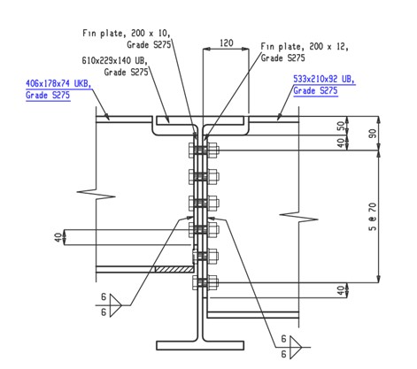
Figure 1. Example 1 – Partial Depth End Plate – Beam to Beam
Connection design report output from SDS2 for this connection:
Note: To view the 3D model (U3D) of the structural joint in the PDF files, open the PDF using Bluebeam or Adobe Acrobat Reader.
Validation Method
The connection as shown in the Simple Joints to Eurocode 3, section 4.6, page 32, Example 1 – Partial depth end plate – Beam to beam (see reference 1) was modeled in SDS2 and a connection design report was generated.
The core of this report features a comparison table for each connection limit state, displaying the calculated capacities from both SDS2 and the cited document. The order of the limit state table generally mirrors the sequence in which it was presented in the Simple Joints to Eurocode 3 example problem. This table also highlights the percent difference (% Δ) between these calculated values, providing a clear measure of any discrepancy, if any.
To further enhance understanding, this report includes relevant notes that discuss any differences or assumptions made during the calculation process. This comparative study's goal is to evaluate the precision and efficiency of the SDS2 connection design software in contrast to the published Eurocode 3 UK design example and serves as a guide for better understanding and application of these design calculations.
Comparison
A comparison of the limit state checks is presented in Table 1. The limit state checks and calculated values aligned well between the published Eurocode 3 UK design example document and the calculation generated by SDS2. The minor differences in calculated values, except where noted, were a result of rounding differences.
Other minor differences are discussed in the comparison table notes.
|
Table 1. Capacity comparison table for Eurocode 3 UK |
||||
|
Limit state on right partial depth end plate |
SDS2 Capacity |
SCI Capacity |
%Δ |
Notes |
|---|---|---|---|---|
|
Supported beam-web shear |
620.6 kN |
621.0 kN |
-0.1% |
|
|
Supported beam-resistance at notch |
137.8 kN-m |
140.0 kN-m |
-1.6% |
|
|
Supported beam-local stability of notched beam |
|
|
- |
|
|
Connection-bolt shear |
94.0 kN / bolt |
94.0 kN / bolt |
0.0% |
|
|
Connection-bearing on plate |
891.1 kN |
904.0 kN |
-1.4% |
|
|
Connection-bearing on support |
891.1 kN |
|
|
|
|
Connection-gross shear yielding |
1290.2 kN |
1290.0 kN |
0.0% |
|
|
Connection-net shear rupture |
1539.1 kN |
1539.0 kN |
0.0% |
|
|
Connection-block tearing |
1195.0 kN |
1195.0 kN |
0.0% |
|
|
Supporting member-shear |
1022.2 kN |
742.0 kN |
27.4% |
|
Table Notes
Note 1: These checks are performed in both SDS2 & Simple Joints to Eurocode 3, but no capacity is calculated.
Note 2: SDS2 includes the long joint effects from section 3.8 of BS EN 1993-1-8_2005, equation 3.5. Simple Joints to Eurocode 3 does not include this effect.
Note 3: Simple Joints to Eurocode 3 performs this check as a part of the supporting beam shear and bearing check (“Supporting member-shear"). SDS2 checks this limit state independently.
Note 4: For supporting member shear to a beam web SDS2 uses half the supporting member web thickness to check the shear for each supported member individually. Simple Joints to Eurocode 3 checks the supporting member shear for the combined supported member loads against the supporting member web thickness.
Note 5: SDS2 conservatively uses half the supporting member web thickness to calculate the shear capacity of the supporting web when there is an opposite connection. Simple Joints to Eurocode 3 uses the full supporting member web thickness to calculate the shear capacity and compares this to the combined supported member loads.
References
- Angle Web Cleats – Beam to Column
- Fin Plates – Beam to Beam (left beam connection)
- Fin Plates – Beam to Beam (right beam connection)
- Fin Plates – Beam to Column Web – Tying Resistance
- Partial Depth End Plate – Beam to Beam (left beam connection)
- Partial Depth End Plate – Beam to Column Web – Tying Resistance
- Full Depth End Plate – Beam to Column
- Moment End Plate

