 Keyboard Shortcut Editor ( Modeling & Drawing Editor , ' Classic ' or ' Lighting ')
Also see (lightning) :
- Customize Interface ( Keyboard Shortcut Editor is opened from)
- Keyboard shortcut configuration ( Keyboard Shortcut Editor can edit one such file at a time)
- Role configuration file (may contain multiple roles)
- Role switcher (each role has an associated keyboard configuration file)
- A role (may be assigned 1 keyboard shortcut configuration, but other roles can have the same keyboard shortcut configuration)
- Lightning role configuration (role configuration file loaded when, for example, Modeling is launched)
- Note: A single keyboard shortcut file can be used across various roles in a role configuration.
Also see (classic) :
- Disable typed dimensions during point location ( User and Site Options > General > )
- Toolbar configuration file (' Classic ' keyboard shortcuts reside in)
- User and Site Options > Toolbars > Drawing Editor (default configuration file loaded at startup)
- User and Site Options > Toolbars > Modeling (default configuration file loaded at startup)
- Load Configuration (to load a configuration other than the default)
- Delete Toolbar Configuration (to delete a configuration)
page 1 | contents | customize interface > keyboard config > edit | settings > | top
Tips for naming and remembering keyboard shortcuts :
User and Site Options > General > "
Disable typed dimensions during point location " disables the capability to type in a distance and/or angle . This permits you to use numerical keyboard shortcuts during point location. If you leave the option not checked (
), do not assign numbers as keyboard shortcuts for operations that might be invoked during point location.
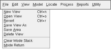
Any keyboard shortcuts that you add here are automatically listed to the right of the associated command on the appropriate drop-down menu (classic). If you add more than one shortcut for the same command, only the shortest is listed.
classic 

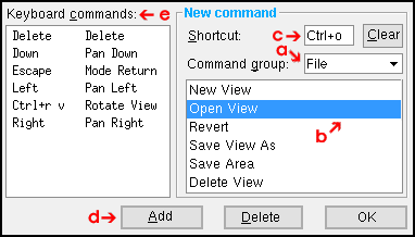
A complete list of keyboard shortcuts for the program you are in (for example, Modeling ) can be found on the " Keyboard commands " list on this window.
Keyboard shortcuts defined here are for Modeling and Drawing Editor operations. You cannot use them on review windows such as the Beam Review window.
Keep your keyboard shortcuts short. That way they are easier to remember, take up less space on menus and require fewer keystrokes.
A shortcut can be a particular character ( o ), or a sequence of characters ( o p e n ) or a character plus a modifier key ( Ctrl + o ).
On the menu, a space separates each character. For example, s p c means "press s then p then c."
The + symbol signifies that you need to hold down a modifier key while pressing a particular key. For example, Ctrl+z means "hold down the Ctrl key and press z", Shift + Z means "hold down the Shift key and press Z."
Ctrl and Shift can be used as modifier keys. The Alt key cannot be used as a modifier key for a keyboard shortcut because the key is already for accelerator keys. For example, in Modeling Alt + f opens the File menu.
On the menu, words are used for keys denoted by symbols for which there are no font characters. For example: Spacebar (for a blank space), Up (for up arrow), Right (for right arrow).
A single word is used for keys that are made up of two words. For example: PgUp (for the Page Up key), Num_Lock (for the Num Lock key).
Function keys ( F1 , F2 , F3 , etc.) can also used as keyboard shortcuts.
When assigning keyboard shortcuts, do not type in a sequence of letters that is also the first part of a sequence that is currently assigned.
Use the same character strings as keyboard shortcuts for tools that are similar in Modeling and the Drawing Editor . For example, use Ctrl + o for both Open File in the Drawing Editor and Open View in Modeling .
page 1 | contents | customize interface > keyboard config > edit | settings > | top
| Command groups in Modeling : File | File - Views/Grids | Edit | Edit - Search | View | View - Solids Mode | View - Tiles | Navigate | Navigate - Navigation Mode | Navigate - Surface Mode | Model | Model - Construction Lines | Model - Construction Circles | Model - Member | Model - Group Member | Model - Material | Model - Hole | Model - Bolt | Model - Weld | Model - Reference Drawing | Model - Parametric | Model - Cranes | Model - Concrete | Locate | Process | Reports | Reports - SDS2 User | Reports -- Viewer | Interface | Settings | Settings - Job Settings | Settings - Fabricator Settings | Settings - Concrete Settings | Miscellaneous | Selection | |
| Erection View Detailing : File | View - Tiles | Navigate | Navigate - Navigation Mode | Navigate - Surface Mode | Settings | User Modes | Selection | Solids | |
page 1 | contents | customize interface > keyboard config > edit | settings > | top

