The Seismic Weld Access Holes window ( Job Settings ) (read-only)
Also see :
- Seismic Access Hole (shape file setting for wide flange)
- Seismic moment frame member ( Beam > "
 Seismic " > )
page 1 | contents | home > project settings > job > design > | classic
To open the Seismic Weld Access Holes window :
Method 1 : Home > Project Settings >Job > Design > Seismic Weld Access Holes .
Methods 2, 3 & 4 : In Modeling or the Drawing Editor , choose Settings > Job Settings > Seismic Weld Access Holes (classic), or use a keyboard shortcut , or click the icon.
page 1 | contents | home > project settings > job > design > | classic | top
Options :
Access Hole Type: A or B or C or D or E or F or G or H or I or J or K or L or M or N .
|
A special case: If the local shape file's " Seismic Access Hole " designation is ' None ' for a particular " Section size ," then connection design does not reference this window, but instead uses the the setup values defined for moment connections in Weld Design Settings .
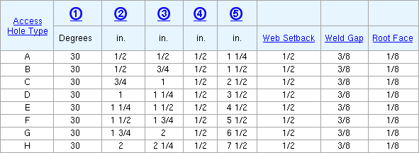
Column (1): 0 to 90 degrees. As specified in the AISC Seismic Design Manual , ' 30 ' is the default groove angle for every " Access Hole Type ." On the left end, '30' bevels the flange 30 degrees clockwise from vertical. On the right end, '30' bevels the flange 30 degrees counterclockwise from vertical. ' 0 ' leaves the top and bottom flanges unleveled.
|
(1) = groove angle. The value entered for (1) applies to both the top and bottom flanges. |
|
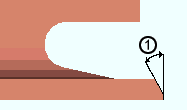
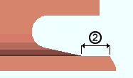
Column (2): The distance measured parallel with the flange from the inside corner of the beveled flange to where the weld access hole is no longer flush with the flange. In the AISC Seismic Design Manual , this value can range from 1/2 inch (for " Access Hole Type " ' A ' and ' B ') to 4 inches (for type ' N ').
|
(2) = flange flush length. The distance along the flange, excluding the beveled portion of the flange, that the web is cut flush to the flange. |
|
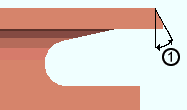
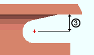
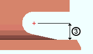
Column (3): Assuming that the beam is horizontal, this is the distance measured perpendicular to the flange (in the primary dimension " Units " or other units ) from the inside of the top or bottom flange to the center of the hole.
|
(3) = flange to hole distance. This is the distance from the inside of the flange to the center of the hole. |
|
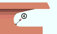
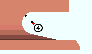
Column (4): The radius of the hole. In the AISC Seismic Design Manual , ' 1/2 ' is the default hole radius for every " Access Hole Type ."
|
(4) = hole radius. |
|
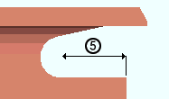
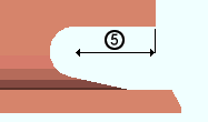
Column (5): The distance measured perpendicular to the web (in the primary dimension " Units " or other units ) from the web to the center of the hole.
|
(5) = web to hole distance. Note that these examples have a " Web setback " and that this distance is measured to the actual edge of the web, after that setback has been applied. |
|
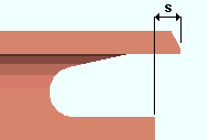
Web Setback: The distance (in the primary dimension " Units " or other units ) from the beam web to the face of the supporting member minus the weld gap .
|
s = web setback. |
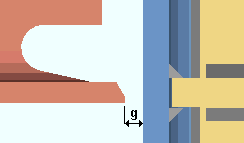
Weld Gap: The distance (in the primary dimension " Units " or other units ) from the edge of the beam's flange to the face of the supporting column.
|
g = weld gap. This example shows doublers and stiffeners in the column. |
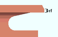
Root Face: The desired root face dimension (in the primary dimension " Units " or other units ) that defines how much of the flange is clipped on welded moment connections.
|
if = root face. |
page 1 | contents | home > project settings > job > design > | classic | top