 Pour Stop Tool
- Tool Summary
- Step-By-Step
- Related Tools
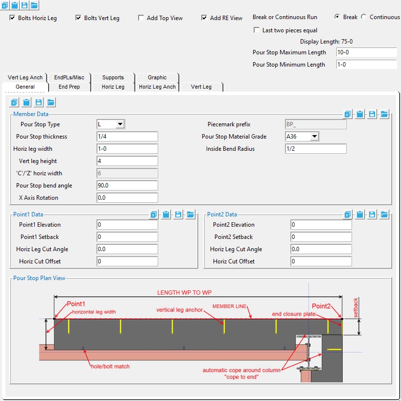
Settings
Bolts Horiz Leg : ![]() or
or ![]() . Same as " Add bolts " under the " Horiz Leg " tab. If this box is checked (
. Same as " Add bolts " under the " Horiz Leg " tab. If this box is checked ( ![]() ), bolts are inserted through the holes in the pour stop horizontal leg and supported member. This option is disabled (grayed out) in the " Horiz Leg " tab when the " Hole spacing type " is ' NONE '.
), bolts are inserted through the holes in the pour stop horizontal leg and supported member. This option is disabled (grayed out) in the " Horiz Leg " tab when the " Hole spacing type " is ' NONE '.
Bolts Vert Leg : ![]() or
or ![]() . Same as " Add bolts " under the " Vert Leg " tab. If this box is checked (
. Same as " Add bolts " under the " Vert Leg " tab. If this box is checked ( ![]() ), bolts are inserted through the holes in the pour stop vertical leg and supported member. This option is disabled (grayed out) in the " Vert Leg " tab when the " Hole spacing type " is ' NONE '.
), bolts are inserted through the holes in the pour stop vertical leg and supported member. This option is disabled (grayed out) in the " Vert Leg " tab when the " Hole spacing type " is ' NONE '.
Add Top View : ![]() or
or ![]() . When the checkbox is checked (
. When the checkbox is checked ( ![]() ), the top view is drawn on the member detail.
), the top view is drawn on the member detail.
Add RE View : ![]() or
or ![]() . When the checkbox is checked (
. When the checkbox is checked ( ![]() ), the right end view is drawn on the member detail.
), the right end view is drawn on the member detail.
Break or Continuous Run : Break or Continuous.
' Break ' splits the pour stop bent plate or angle material into multiple sections. If this option is selected ' Last two pieces equal ' and the ' Pour Stop Maximum and Minimum Length ' options are shown.
' Continuous Run ' keeps the pour stop bent plate material or angle material as a single material the full length of the run.
If the box is checked (
), the length of the last two pour stop members in the run will be the same.
If the box is not checked (
), the length of the last pour stop member in the run may vary.
Pour Stop Maximum Length : The maximum length that any pour stop member created by the ' Pour Stop Tool ' can be.
Pour Stop Minimum Length : The minimum length that any pour stop member created by the ' Pour Stop Tool ' can be.
All other options can be found on the Pour Stop member page.
1 . Invoke Pour Stop Tool by clicking the the Pour Stop Tool icon, which is pictured above. The icon can be found on the Members page > Steel section.
Alternative :Pour Stop Tool can also be invoked using the Find Tool by searching the command name and clicking the Pour Stop Tool icon, which is pictured above.
2 .Locate- Repeat -Return mouse bindings become active along with various Locate options.
Note : The end points you are selecting are at the heel of the bent plate or angle material. The direction the points are selected affects the direction of the horizontal leg. In a plan view, if the points are selected left to right, the horizontal leg toes towards the bottom of the screen. If the points are selected bottom to top, the horizontal leg toes to the right of the screen.
3 . Locate the first point of the pour stop run. The first point selected will be your point1 (similar to the left end for other members) for the first pour stop member.
4 . Locate the end point of the pour stop run. The second point selected will be your point2 (similar to the right end for other members) for the last pour stop member. This second point sets the length of the pour stop run.
5 . The Pour Stop Tool window opens.
5a : Make the appropriate setting changes in the Pour Stop edit window, press " OK " to go to step 6 .
6 . The Pour Stop members are added.
- Pour Stop (member)
- Pour Stop (Component)
- Pour Stop Settings (member settings)

