Pour Stop Member
Adds a bent plate, multi-bend plate, or angle pour stop.
- Tool Summary
- Step-By-Step
- Tips and Tricks
- Related Tools
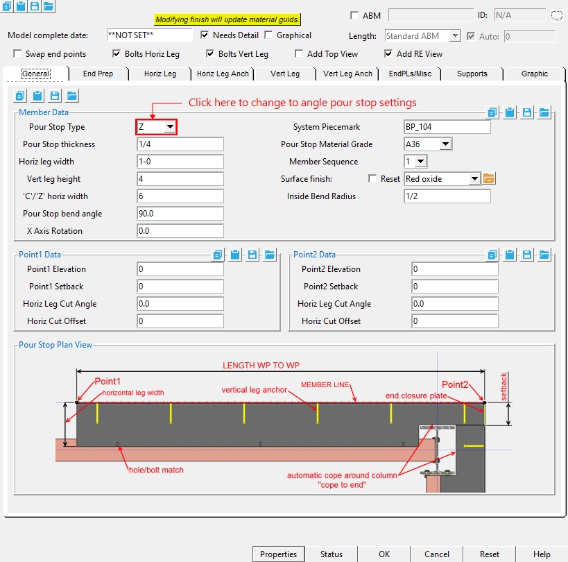
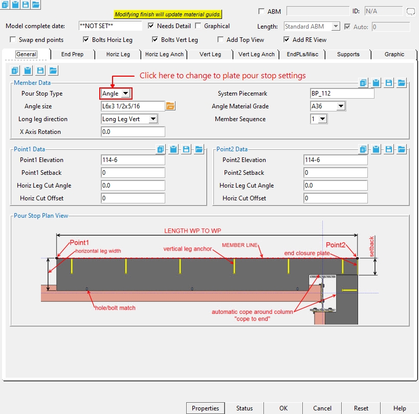
General Tab
Model Complete date : **NOT SET** or a month day year .
means this member will automatically be selected for detailing the next time you Detail Members . All members whose details have not yet been generated or which have been altered in Modeling since the time that their details were generated are automatically marked for detailing.
means that the member has undergone Detail Membersand has not been altered in Modeling since that time. Or it means that the user has switched this button to ' NO ' to prevent a detail from being detailed again.
If the box is checked (
If the box is not checked (
Note: Add Material or Add Hole or Add Bolt does not change the member to graphical (
If the box is checked (
If the box is not checked (
Bolts Horiz Leg :
![]() or
or ![]() . Same as " Add bolts " under the " Horiz Leg " tab. If this box is checked (
. Same as " Add bolts " under the " Horiz Leg " tab. If this box is checked ( ![]() ), bolts are inserted through the holes in the pour stop horizontal leg and supported member. This option is disabled (grayed out) in the " Horiz Leg " tab when the " Hole spacing type " is ' NONE '.
), bolts are inserted through the holes in the pour stop horizontal leg and supported member. This option is disabled (grayed out) in the " Horiz Leg " tab when the " Hole spacing type " is ' NONE '.
Bolts Vert Leg : ![]() or
or ![]() . Same as " Add bolts " under the " Vert Leg " tab. If this box is checked (
. Same as " Add bolts " under the " Vert Leg " tab. If this box is checked ( ![]() ), bolts are inserted through the holes in the pour stop vertical leg and supported member. This option is disabled (grayed out) in the " Vert Leg " tab when the " Hole spacing type " is ' NONE '.
), bolts are inserted through the holes in the pour stop vertical leg and supported member. This option is disabled (grayed out) in the " Vert Leg " tab when the " Hole spacing type " is ' NONE '.
Add Top View : ![]() or
or ![]() . When the checkbox is checked (
. When the checkbox is checked ( ![]() ), the top view is drawn on the member detail.
), the top view is drawn on the member detail.
Add RE View : ![]() or
or ![]() . When the checkbox is checked (
. When the checkbox is checked ( ![]() ), the right end view is drawn on the member detail.
), the right end view is drawn on the member detail.
Member Data
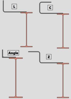
Pour Stop Type :L or C or Z or Angle. The L, C, and Z shapes are bent plate materials, where angle is a rolled section from the shapes file.
Pour Stop thickness : The thickness of this bent plate (in the primary dimension " Units " or other units or the gage ). (Only applicable when the Pour Stop type is set to L, C, or Z).
To enter gage plate: Type in the ' gage number' followed by ' ga ' (example: ' 4ga ' is rewritten as ' 4GA ' when you Tab out of the field). Right-click tells you the stored thickness (based on industry standards), from which the weight of the gage plate is calculated. Allowable gages are any whole number from 3 to 38 .
Thickness precision: You can enter a plate " Material thickness " that is more precise than the " Dimension precision " that is set at Home > Project Settings > Fabricator > Detailing > Drawing Presentaton . For example, if you enter ' 5/32 ' and the " Dimension precision " is ' 1/16 ', the thickness of the plate will be ' 5/32 '. The thickness you enter will be reflected in the " Description " and will propagate to the bill of material, reports, etc. The setup option to " Round flat plate values " does not affect this. Be aware that the Ruler measures to whatever the " Dimension precision " is set to, which means that the plate's measured thickness may not exactly match its actual thickness.
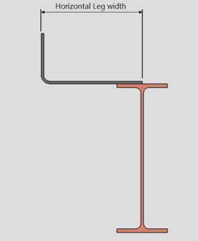
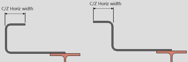
Horiz leg width : The distance (in the primary dimension " Units " or other units ) from the outside face of the vertical leg to the edge of the horizontal leg. (Only applicable when the Pour Stop type is set to L, C, or Z).
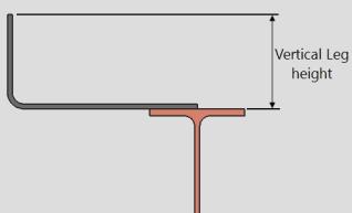
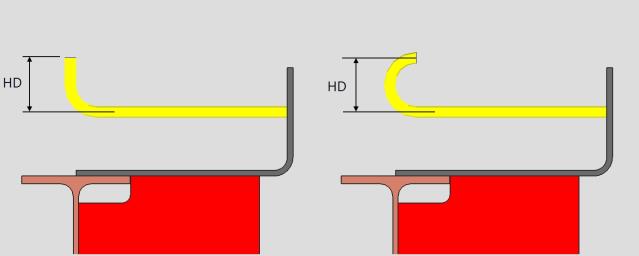
Vert leg height : The distance (in the primary dimension " Units " or other units ) from the outside face of the horizontal leg to the edge of the vertical leg or top of the C/Z width. (Only applicable when the Pour Stop type is set to L, C, or Z).
'C/'Z' horiz width : The distance (in the primary dimension " Units " or other units ) parallel to the horizontal leg width from the outside face of the vertical leg to the edge of the top leg. (Only applicable when the Pour Stop type is set to C or Z).
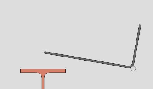
Pour Stop bend angle : The angle (in degrees) between the horizontal leg and the vertical leg. (Only applicable when the Pour Stop type is set to L, C, or Z).
X Axis Rotation : The angle (in degrees) that the whole member is rotated about the member line.
System Piecemark : A text string of up to 61 characters which identifies this member as having a unique design distinct from other members that have been assigned different piecemarks.
Pour Stop Material Grade :A36 or A992 or etc. This " ![]() General settings " option sets the steel grade of the members's main material, whose " Section size " is set on the same member edit window.
General settings " option sets the steel grade of the members's main material, whose " Section size " is set on the same member edit window.
Member Sequence : Any sequence name from the Sequence Names list can be entered here. The sequence applies to this member only.
Defaults: The sequence assigned by default to the first member of the same type (beam, column, etc.) that is added after you first start up Modeling is the sequence listed in line 1 of the Sequence Names list. For each subsequently added member of that type during the same session in Modeling , the default sequence becomes the sequence assigned to the last-added or last-edited member.
To assign a different sequence, you can type in any sequence name that is on the Sequence Names list, or you can press the "file cabinet" browse button (
) and double-click any sequence name that is on the list.
Surface finish :None or Sandblasted or Red oxide or Yellow zinc or Gray oxide or Blued steel or Galvanized or Duplex Coating or Undefined 1 or Undefined 2 or Undefined 3 or Red oxide 2 or Any user added surface finish. This affects the colors of 'Solid ' members on erection views in the Drawing Editor . This also sets the color when "Output material color " is set to 'Surface finish ' for a VRML Export or a DWG/DXF Export . The "Color " ( not "Surface finish ") sets the color of this material in Modeling .
| sand blasted | red oxide | yellow zinc | user surface finish 1 |
| gray oxide | blued steel | galvanized | user surface finish 2 |
To assign a different surface finish, you can drop-down the current surface finish and select the one you want, or you can press the "file cabinet" browse button (
) and double-click any surface finish that is on the list.
Inside Bend Radius : The radius (in the primary dimension " Units " or other units ) at the inside of each bend for L, C, and Z shapes.
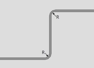
R = Inside Bend Radius
General Tab - Angle
Pour Stop Type :L or C or Z or Angle. The L, C, and Z shapes are bent plate materials, where angle is a rolled section from the shapes file.
Angle Size : Any Angle " Section size " that is maintained in the local shape file. (Only applicable when the Pour Stop type is set to Angle).
Long leg direction : Long leg Vert or Long leg Horiz. (Only applicable when the Pour Stop type is set to Angle).
' Long leg Vert' orients the long leg of the angle vertically.
' Long leg Horiz' orients the long leg of the angle horizontally.
X Axis Rotation : The angle (in degrees) that the whole member is rotated about the member line.
System Piecemark : A text string of up to 61 characters which identifies this member as having a unique design distinct from other members that have been assigned different piecemarks.
Angle Material Grade :A36 or A992 or etc. This " ![]() General settings " option sets the steel grade of the members's main material, whose " Section size " is set on the same member edit window.
General settings " option sets the steel grade of the members's main material, whose " Section size " is set on the same member edit window.
Member Sequence : Any sequence name from the Sequence Names list can be entered here. The sequence applies to this member only.
Defaults: The sequence assigned by default to the first member of the same type (beam, column, etc.) that is added after you first start up Modeling is the sequence listed in line 1 of the Sequence Names list. For each subsequently added member of that type during the same session in Modeling , the default sequence becomes the sequence assigned to the last-added or last-edited member.
To assign a different sequence, you can type in any sequence name that is on the Sequence Names list, or you can press the "file cabinet" browse button (
Point1 / Point2 Data
Point1/Point2 Elevation : The elevation (in the primary dimension " Units " or other units ) of the work point at this end of the pour stop. For a non-sloping plate, both the left and right end elevations are the same. When you add the pour stop, its work points are placed in your current view's reference elevation until you change their elevations here, on this window.
Point1/Point2 Setback : The positive or negative (-) distance that you want the (left or right) end of the pour stop to be displaced from its work point.
A ' positive setback ' makes the pour stop shorter. The distance is subtracted from the work point distance.
A ' negative (-) setback ' makes the pour stop longer. The negative distance is added to the work point distance.
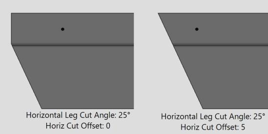
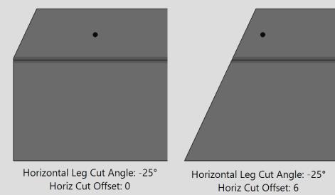
Horiz Leg Cut Angle : Any positive or negative (-) angle measured in degrees ( 89 to -89 ). The cut is is made on the horizontal leg.
Point1 Point2 Point1 & Point2 Point1 Point2 -10 degrees -10 degrees 0 degrees 10 degrees 10 degrees Point 1 cut: If the left end of the bent plate is to your left on your computer screen and negative distances along its Y member axis are toward the bottom of the screen: ' 0 ' (zero) square cuts the end. A ' positive angle ' is measured counterclockwise from a perpendicular bisector to the member line. A ' negative (-) angle ' is measured clockwise from a perpendicular bisector to the member line.
Point 2 cut : If the left end of the bent plate is to your left on your computer screen and positive distances along its Z member axis are toward the top of the screen: ' 0 ' (zero) square cuts the end. A ' positive angle ' is measured counterclockwise from a perpendicular bisector to the member line. A ' negative (-) angle ' is measured clockwise from a perpendicular bisector to the member line.
Note : When the ' Pour Stop Type ' is set to ' C or Z ', the cut by default will only pass through the horizontal leg or c/z horizontal leg.
Horiz Cut Offset : The distance (in the primary dimension " Units " or other units ) from point1 / point2 along the member line to offset where the cut begins. This is especially useful when the ' Pour Stop Type ' is set to ' C or Z. '
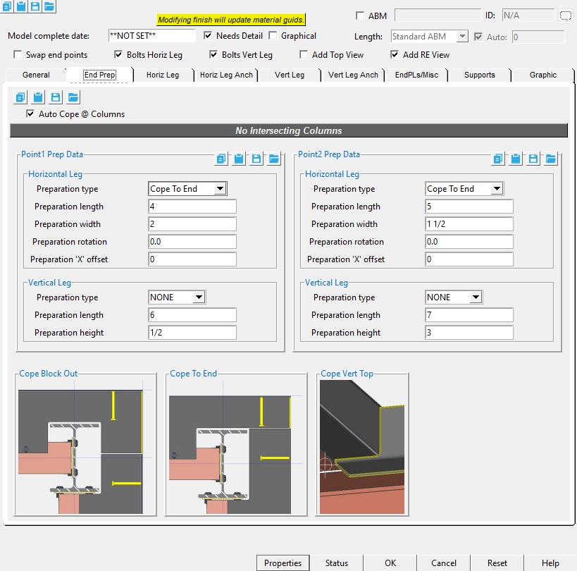
End Prep Tab
Auto Cope @ Columns : ![]() or
or ![]() . If checked, the member automatically copes the pour stop main material around any intersecting columns. The Horizontal Leg values below will be read only.
. If checked, the member automatically copes the pour stop main material around any intersecting columns. The Horizontal Leg values below will be read only.
Horizontal Leg
Preparation type :NONE or Cope To End or Cope Block Out. This is only able to be edited if Auto Cope @ Columns is unchecked (  ).
).
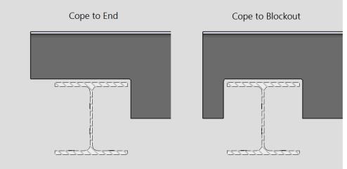
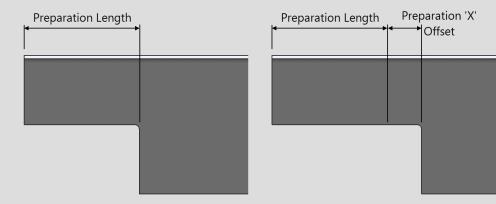
Cope to End : Expands the cope from the end of the main material for Point1 or Point2, to the preparation length + Preparation 'X' offset.
Cope to Blockout : Places the cope centered at the Preparation 'X' offset, and then the length is set by the preparation length on either side of the center point. For example, if a 3" preparation length is set, the overall width of the cope will be 6".
Preparation length : Sets the length of the cope along the span of the member line from the left/right end of the main material.
Preparation width : Sets the width (depth) of the cope from the top/bottom edge of the main material toward its center.
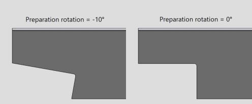
Preparation rotation : Sets the rotation of the cope at the preparation 'X' Offset. A positive (+) value rotates this counter-clockwise, while a negative (-) value rotates this clockwise.
Preparation 'X' offset : The distance the cope moves along the span of the member line from the left/right end of the main material.
Vertical Leg
Preparation type :NONE or Cope Top or Cope Bott.
Cope Top: adds a cope at the top of the vertical leg on the main material.
Cope Bott: adds a cope at the bottom of the vertical leg on the main material. Setting a cope on the bottom will cope the full width of the horizontal leg.
Preparation length : Sets the length of the cope along the span of the member line from the left/right end of the main material.
Preparation height : Sets the height (depth) of the cope along the span of the member line from the bottom/top of the main material. When using cope bott, the distance will be from the bottom side of the main material.
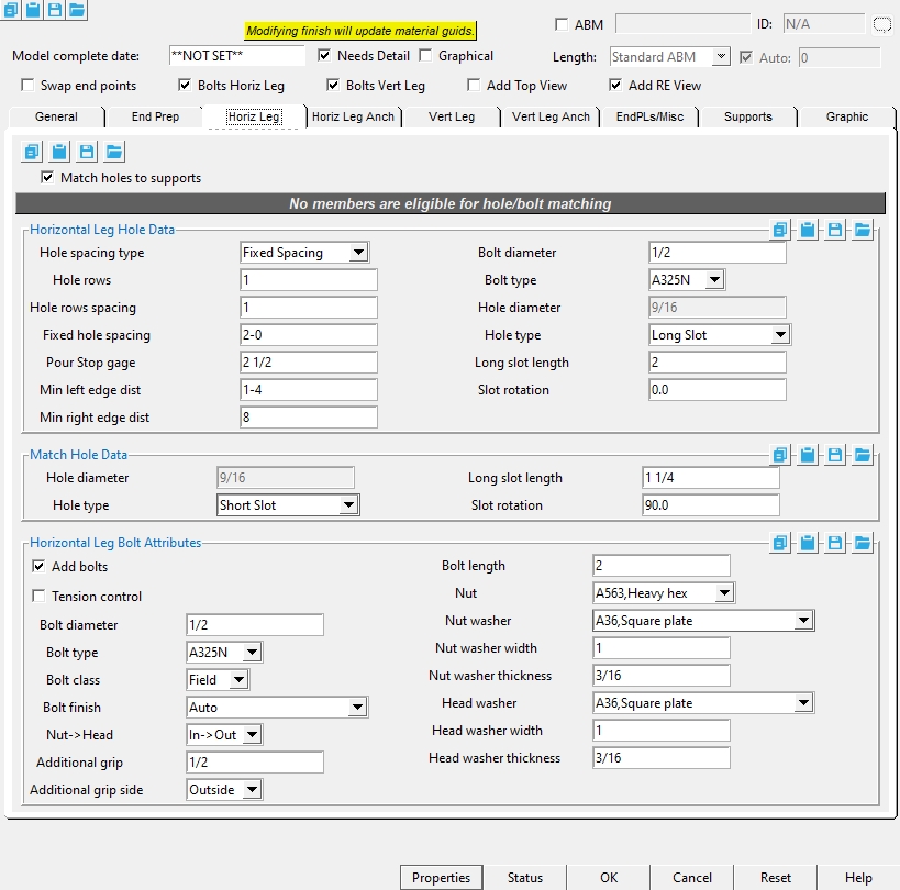
Horiz Leg Tab
Match holes to supports : ![]() or
or ![]() . When the checkbox is checked (
. When the checkbox is checked ( ![]() ), the holes from the pour stop will be matched to the supporting beam.
), the holes from the pour stop will be matched to the supporting beam.
Horizontal Leg Hole Data
Hole spacing type : NONE or Fixed Spacing or Maximum Spacing.
NONE : Means there are no holes added to the pour stop horizontal leg.
Fixed Spacing: Sets the exact distance between the holes in the horizontal leg. When Fixed spacing is set, you then set a minimum distance from the left edge, and right edge of the pour stop and the Fixed Hole Spacing.
Maximum Spacing : Sets the exact distance the first hole is located from the left edge, and right edge of the pour stop. This then uses the Max Hole spacing to set the distance between holes equally.
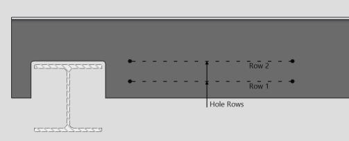
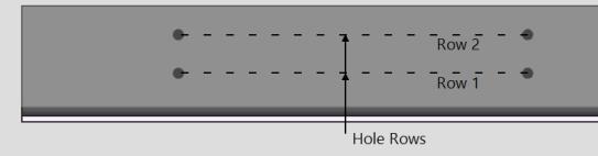
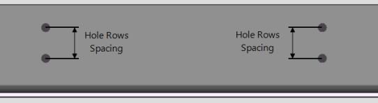
Hole rows : The number of hole rows. Hole rows run parallel with the work line of the pour stop.
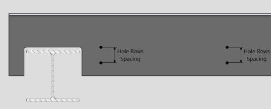
Hole rows spacing : A center-to-center distance between adjacent " Rows " of holes.
Fixed hole spacing : A set center-to-center distance between holes along the length of the pour stop member. (Only applicable when the Hole spacing type is set to Fixed Spacing)
Min left edge dist : When the hole spacing type is " Fixed Spacing ". The hole that is nearest to the left end of the pour stop will be placed at least this distance away from the left-end workpoint of the pour stop.
Min right edge dist : When the hole spacing type is " Fixed Spacing ". The hole that is nearest to the right end of the pour stop will be placed at least this distance away from the right-end workpoint of the pour stop.
Maximum Hole Spacing Settings :
Max hole spacing : A maximum center-to-center distance between holes along the length of the pour stop member. (Only applicable when the Hole spacing type is set to Maximum Spacing)
Fixed left edge dist : When the hole spacing type is " Maximum Spacing ". The hole that is nearest to the left end of the pour stop will be placed this distance away from the left-end workpoint of the pour stop.
Fixed right edge dist : When the hole spacing type is " Maximum Spacing ". The hole that is nearest to the right end of the pour stop will be placed this distance away from the right-end workpoint of the pour stop.
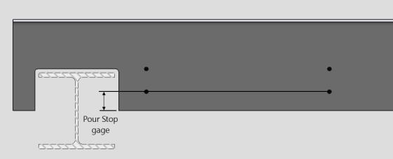
Pour Stop gage : The vertical distance from the far side of the horizontal leg to the 1st hole row.
Bolt diameter : The diameter (inches or mm) of the shank of the bolt. This applies even if you have not elected to " Add bolts " since the diameter that you enter here together with the " Hole type " sets the " Hole diameter ."
diameter
Bolt type : A325N or A325SC or A325X , etc. The bolt types that you can choose in the list box ( ![]() ) are the bolt types that are listed at Home > Project Settings > Job > Bolt Specifications .
) are the bolt types that are listed at Home > Project Settings > Job > Bolt Specifications .
Hole diameter :read-only . The hole size that is reported here is calculated automatically based on the " Hole type " and the " Bolt diameter ."
Hole type : Standard round or Short slot or Oversized round or Long slot or Cope hole or Erection pin hole or Anchor bolt hole or Plug weld hole. For a more thorough explanation of each of these types, see " Hole type " on the Hole Edit window.

All hole types work together with the " Bolt diameter " to set the " Hole diameter ."
' Short slot ' sets the " Slot length " to be a particular length.
' Long slot ' allows the user to set the " Long Slot length ."
Long slot length : The distance (in the primary dimension " Units " or other units ) between the two points farthest from one another on the perimeter of a slot. This applies when the " Hole type " is ' Long slot '.
| slot length |
|
|
Slot rotation : A positive or negative number from 90 to -90 degrees. This applies when the " Hole type " is ' Long slot ' or ' Short slot '. Slot rotations can be modeled to a precision of 0.1 degree.
| when the hole group X axis
is horizontal (<==>) |
when the hole group X axis
is vertical |
Match Hole Data
Hole diameter :read-only . The hole size that is reported here is calculated automatically based on the " Hole type " and the " Bolt diameter ."
Hole type : Standard round or Short slot or Oversized round or Long slot or Cope hole or Erection pin hole or Anchor bolt hole or Plug weld hole. This is the hole type for the supporting beam matched hole. For a more thorough explanation of each of these types, see " Hole type " on the Hole Edit window.
All hole types work together with the " Bolt diameter " to set the " Hole Diameter ."
' Short slot ' sets the " Slot length " to be a particular length.
' Long slot ' allows the user to set the " Long Slot length ."
Long slot length : The distance (in the primary dimension " Units " or other units ) between the two points farthest from one another on the perimeter of a slot. This applies when the " Hole type " is ' Long slot '.
| slot length |
|
|
Slot rotation : A positive or negative number from 90 to -90 degrees. This applies when the " Hole type " is ' Long slot ' or ' Short slot '. Slot rotations can be modeled to a precision of 0.1 degree.
| when the hole group X axis
is horizontal (<==>) |
when the hole group X axis
is vertical |
Horizontal Leg Bolt Attributes
If this box is checked (
If the box is not checked (
If this box is checked (
If the box is not checked (
Bolt diameter : The diameter (inches or mm) of the shank of the bolt. This applies even if you have not elected to " Add bolts " since the diameter that you enter here together with the " Hole type " sets the " Hole diameter ." This field is directly linked to the " Bolt Diameter " that is set in the Horizontal Leg Hole Data, If either is changed the other updates.
diameter 
Bolt type : A325N or A325SC or A325X , etc. The bolt types that you can choose in the list box ( ![]() ) are the bolt types that are listed at Home > Project Settings > Job > Bolt Specifications .
This field is directly linked to the " Bolt type " that is set in the Horizontal Leg Hole Data, If either is changed the other updates.
) are the bolt types that are listed at Home > Project Settings > Job > Bolt Specifications .
This field is directly linked to the " Bolt type " that is set in the Horizontal Leg Hole Data, If either is changed the other updates.
Bolt class : Automatic or Field or Shop.
If ' Automatic ' is selected, the horizontal leg bolts use the " Default bolt class " that is set at Home > Project Settings > Job > Bolt Settings .
If ' Field ' is selected, ' Field ' is assigned as the " Bolt class " to all bolts that fasten on the horizontal leg.
If ' Shop ' is selected, ' Shop ' is assigned as the " Bolt class " to all bolts that fasten on the horizontal leg.
Bolt finish : Auto or Black or Mechanically galvanized or Hot dipped galvanized .
Note: When the member's surface finish is Galvanized, if the "Bolt finish" is set to Auto, the bolt finish will default to Project Settings > Detailing > Galvanizing Settings > Connections > Bolt finish
Nut -> Head :In -> Out or Out -> In.
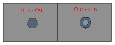
In -> Out : Select ' In -> Out ' if you want the head of the bolt on top of the pour stop member.
Out -> In : Select ' Out -> In ' if you want the nut on the top of the pour stop member.
Additional grip :The distance added between the inside of the bolt head and inside of the nut. If there are washers on the bolt, the bolt grip is measured from the inside of the washers.
g = grip Note : This option is only used when "Match holes to supports" is unchecked. If "Match holes to supports" is checked, the system calculates this value.
Additional grip side : Inside or Outside
Inside : Sets the nut side flush to the bottom of the connection.
Outside : Sets the bolt head side flush to the top of the bent plate.
Note : This option is only used when "Match holes to supports" is unchecked. If "Match holes to supports" is checked, the system calculates this value.
Bolt length : The distance from the inside of the bolt head to the end of the bolt shank. The bolt' s head thickness is not included in the calculation of bolt length because head thickness may vary among bolt manufacturers.
| length |
|
Note : If "Match holes to supports" is checked, the length that is automatically entered here is calculated based on the thickness of the materials into which the bolt is inserted, the number and thickness of washers, the thickness of the nut, and the amount of additional grip. If "Match holes to supports" is unchecked, the system uses the user entered value.
Nut : NONE or A563, Heavy hex or A563-C, Heavy hex or A563-DH, Heavy hex or A194, Heavy hex.


heavy hex nut
Nut washer : NONE or F436,Hardened or F436,Flat or F436,Bevel or F959,Direct tension indicator or A36,Square plate or A36,Round plate or A536-84,Hillside or A36,Material plate .
| type | shape | BOM | thickness |
| bevel |
|
BVL |
" Bevel washers "
( Home > Project Settings > Job > Washer Settings ) |
| square
plate |
|
PL |
" Nut washer thickness "
(see below) |
| round
plate |
|
RPL |
" Nut washer thickness "
(see below) |
| direct tension indicator |
|
DTI |
" Direct tension indicator "
( Home > Project Settings > Job > Washer Settings ) |
| hillside |
|
HLS | - |
| flat |
|
FL |
" Flat washers "
( Home > Project Settings > Job > Washer Settings ) |
| hardened |
|
HD |
" Hardened washers "
( Home > Project Settings > Job > Washer Settings ) |
Nut washer width : The length or width of a square plate washer, or the diameter of a round plate washer.
w = width
Nut washer thickness :The thickness of the square plate or round plate washer.
t = thickness
Head washer : NONE or F436,Hardened or F436,Flat or F436,Bevel or F959,Direct tension indicator or A36,Square plate or A36,Round plate or A536-84,Hillside or A36,Material plate .
| type | shape | BOM | thickness |
| bevel |
|
BVL |
" Bevel washers "
( Home > Project Settings > Job > Washer Settings ) |
| square
plate |
|
PL |
" Nut washer thickness "
(see below) |
| round
plate |
|
RPL |
" Nut washer thickness "
(see below) |
| direct tension indicator |
|
DTI |
" Direct tension indicator "
( Home > Project Settings > Job > Washer Settings ) |
| hillside |
|
HLS | - |
| flat |
|
FL |
" Flat washers "
( Home > Project Settings > Job > Washer Settings ) |
| hardened |
|
HD |
" Hardened washers "
( Home > Project Settings > Job > Washer Settings ) |
Head washer width : The length or width of a square plate washer, or the diameter of a round plate washer.
w = width
Head washer thickness : The thickness of the square plate or round plate washer.
t = thickness
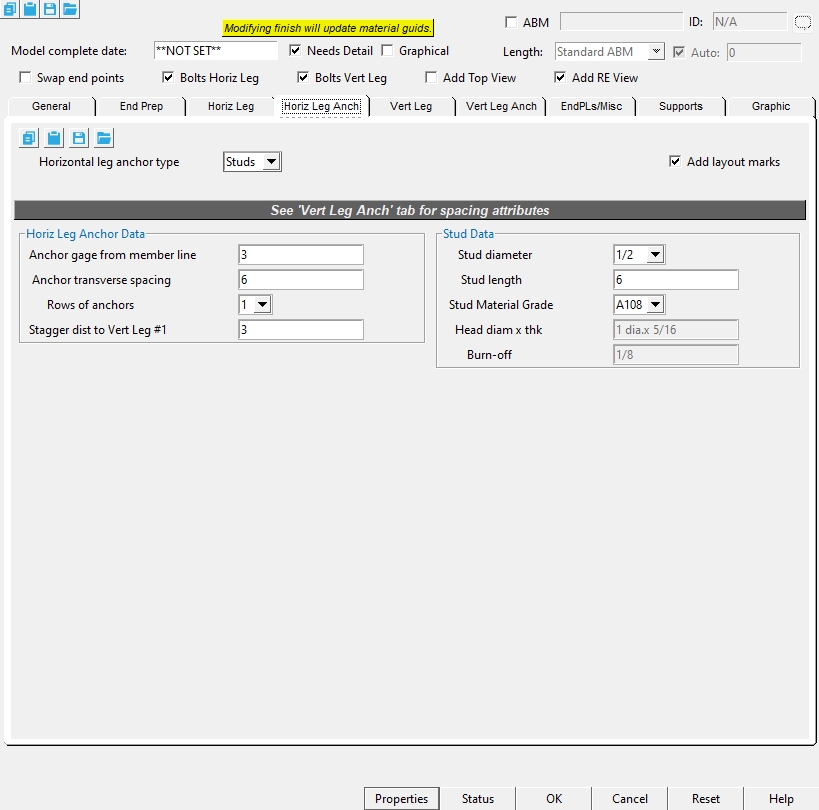
Horizontal Leg Anch Tab
Horizontal leg anchor type : Studs or NONE.
Add layout marks : ![]() or
or ![]() . This is known as CNC Marks.
. This is known as CNC Marks.
If this box is checked (
Horizontal Leg Anchor Data
Anchor gage from member line : Distance from the toe of the horizontal leg, similar to Pour Stop gage.
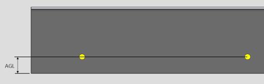
AGL = anchor gage from member line
Anchor transverse spacing : A center-to-center distance between adjacent " Rows " of anchors.
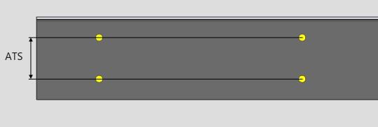
ATS = Anchor transverse spacing
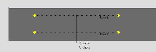
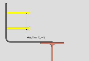
Rows of anchors : The number of anchor rows.
Stagger dist to Vert Leg #1 : The distance the studs are staggered from the anchor locations for the vertical leg of
the pour stop.
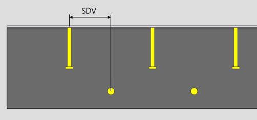
SDV = Stagger dist to Vert Leg #1
Stud Data
Stud diameter : The rod diameter of the shear stud or threaded stud.
Stud length : The distance between the two ends of the shear stud or threaded stud. The head is included in the length of a shear stud.
Stud Material Grade : A108 or A493 or etc. This is the grade of steel for the shear stud or threaded stud whose settings are defined on this window.
Setup: If the grade of steel you want is not shown in the list box (
), you can use Home > Project Settings > Job > Shear and Threaded Stud Grades to add it to this list.
Head diam x thk : (read-only) The diameter of the shear stud's head by the thickness of the head.
Burn-off : (read-only) the reduction in length of a weld stud, which occurs during the arc stud welding process.
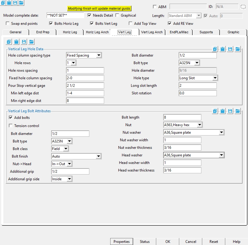
Vert Leg Tab
Vertical Leg Hole Data
Hole column spacing type : NONE or Fixed Spacing or Maximum Spacing.
NONE : Means there are no holes added to the pour stop vertical leg.
Fixed Spacing: Sets the exact distance between the holes in the vertical leg. When Fixed spacing is set, you then set a minimum distance from the left edge, and right edge of the pour stop and the Fixed Hole Spacing.
Maximum Spacing : Sets the exact distance the first hole is located from the left edge, and right edge of the pour stop. This then uses the Max Hole spacing to set the distance between holes equally.
Hole rows : The number of hole rows. Hole rows run parallel with the work line of the pour stop.
Hole rows spacing : A center-to-center distance between adjacent " Rows " of holes.
Fixed hole column spacing : A set center-to-center distance between holes along the length of the pour stop member. (Only applicable when the Hole spacing type is set to Fixed Spacing)
Min left edge dist : When the hole spacing type is " Fixed Spacing ". The hole that is nearest to the left end of the pour stop will be placed at least this distance away from the left-end workpoint of the pour stop.
Min right edge dist : When the hole spacing type is " Fixed Spacing ". The hole that is nearest to the right end of the pour stop will be placed at least this distance away from the right-end workpoint of the pour stop.
Maximum Hole Spacing Settings :
Max hole column spacing : A maximum center-to-center distance between holes along the length of the pour stop member. (Only applicable when the Hole spacing type is set to Maximum Spacing)
Fixed left edge dist : When the hole spacing type is " Maximum Spacing ". The hole that is nearest to the left end of the pour stop will be placed this distance away from the left-end workpoint of the pour stop.
Fixed right edge dist : When the hole spacing type is " Maximum Spacing ". The hole that is nearest to the right end of the pour stop will be placed this distance away from the right-end workpoint of the pour stop.
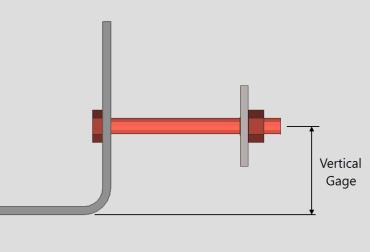
Pour Stop vertical gage : The vertical distance from the bottom side of the pour stop to the 1st hole row.
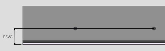
PSVG = Pour Stop vertical gage from member line
Bolt diameter : The diameter (inches or mm) of the shank of the bolt. This applies even if you have not elected to " Add bolts " since the diameter that you enter here together with the " Hole type " sets the " Hole diameter ."
diameter
Bolt type : A325N or A325SC or A325X , etc. The bolt types that you can choose in the list box ( ![]() ) are the bolt types that are listed at Home > Project Settings > Job > Bolt Specifications .
) are the bolt types that are listed at Home > Project Settings > Job > Bolt Specifications .
Hole diameter : read-only . The hole size that is reported here is calculated automatically based on the " Hole type " and the " Hole diameter ."
Hole type : Standard round or Short slot or Oversized round or Long slot or Cope hole or Erection pin hole or Anchor bolt hole or Plug weld hole. For a more thorough explanation of each of these types, see " Hole type " on the Hole Edit window.
All hole types work together with the " Bolt diameter " to set the " Hole diameter ."
' Short slot ' sets the " Slot length " to be a particular length.
' Long slot ' allows the user to set the " Long Slot length ."
Long slot length : The distance (in the primary dimension " Units " or other units ) between the two points farthest from one another on the perimeter of a slot. This applies when the " Hole type " is ' Long slot '.
| slot length |
|
|
Slot rotation : A positive or negative number from 90 to -90 degrees. This applies when the " Hole type " is ' Long slot ' or ' Short slot '. Slot rotations can be modeled to a precision of 0.1 degree.
| when the hole group X axis
is horizontal (<==>) |
when the hole group X axis
is vertical |
Vertical Leg Bolt Attributes
If this box is checked (
If the box is not checked (
If this box is checked (
If the box is not checked (
Bolt diameter : The diameter (inches or mm) of the shank of the bolt. This applies even if you have not elected to " Add bolts " since the diameter that you enter here together with the " Hole type " sets the " Hole diameter ." This field is directly linked to the " Bolt Diameter " that is set in the Horizontal Leg Hole Data, If either is changed the other updates.
diameter
Bolt type : A325N or A325SC or A325X , etc. The bolt types that you can choose in the list box ( ![]() ) are the bolt types that are listed at Home > Project Settings > Job > Bolt Specifications .
This field is directly linked to the " Bolt type " that is set in the Horizontal Leg Hole Data, If either is changed the other updates.
) are the bolt types that are listed at Home > Project Settings > Job > Bolt Specifications .
This field is directly linked to the " Bolt type " that is set in the Horizontal Leg Hole Data, If either is changed the other updates.
Bolt class : Automatic or Field or Shop.
If ' Automatic ' is selected, the vertical leg bolts use the " Default bolt class " that is set at Home > Project Settings > Job > Bolt Settings .
If ' Field ' is selected, ' Field ' is assigned as the " Bolt class " to all bolts that fasten on the horizontal leg.
If ' Shop ' is selected, ' Shop ' is assigned as the " Bolt class " to all bolts that fasten on the horizontal leg.
Bolt finish :Auto or Black or Mechanically galvanized or Hot dipped galvanized .
Note: When the member's surface finish is Galvanized, if the "Bolt finish" is set to Auto, the bolt finish will default to Project Settings > Detailing > Galvanizing Settings > Connections > Bolt finish
Nut-> Head :In -> Out or Out -> In.
In -> Out : Select ' In -> Out ' if you want the head of the bolt on top of the pour stop member.
Out -> In : Select ' Out -> In ' if you want the nut on the top of the pour stop member.
Additional grip : The distance added between the inside of the bolt head and inside of the nut. If there are washers on the bolt, the bolt grip is measured from the inside of the washers.
g = grip
Additional grip side : Inside or Outside
Inside : Sets the nut side flush to the bottom of the connection.
Outside :Sets the bolt head side flush to the top of the bent plate.
Bolt length : The distancefrom the inside of the bolt head to the end of the bolt shank. The bolt' s head thickness is not included in the calculation of bolt length because head thickness may vary among bolt manufacturers.
length 
Note : If "Match holes to supports" is checked, the length that is automatically entered here is calculated based on the thickness of the materials into which the bolt is inserted, the number and thickness of washers, the thickness of the nut, and the amount of additional grip. If "Match holes to supports" is unchecked, the system uses the user entered value.
Nut :NONE or A563, Heavy hex or A563-C, Heavy hex or A563-DH, Heavy hex or A194, Heavy hex.
heavy hex nut
Nut washer : NONE or F436,Hardened or F436,Flat or F436,Bevel or F959,Direct tension indicator or A36,Square plate or A36,Round plate or A536-84,Hillside or A36,Material plate .
type shape BOM thickness bevel 
BVL " Bevel washers "
( Home > Project Settings > Job > Washer Settings )square
plate
PL " Nut washer thickness "
(see below)round
plate
RPL " Nut washer thickness "
(see below)direct tension
indicator
DTI " Direct tension indicator "
( Home > Project Settings > Job > Washer Settings )hillside HLS - flat FL " Flat washers "
( Home > Project Settings > Job > Washer Settings )hardened HD " Hardened washers "
( Home > Project Settings > Job > Washer Settings )
Nut washer width : The length or width of a square plate washer, or the diameter of a round plate washer.
w = width
Nut washer thickness : The thickness of the square plate or round plate washer.
t = thickness
Head washer : NONE or F436,Hardened or F436,Flat or F436,Bevel or F959,Direct tension indicator or A36,Square plate or A36,Round plate or A536-84,Hillside or A36,Material plate .
| type | shape | BOM | thickness |
| bevel |
|
BVL |
" Bevel washers "
( Home > Project Settings > Job > Washer Settings ) |
| square
plate |
|
PL |
" Nut washer thickness "
(see below) |
| round
plate |
|
RPL |
" Nut washer thickness "
(see below) |
| direct tension indicator |
|
DTI |
" Direct tension indicator "
( Home > Project Settings > Job > Washer Settings ) |
| hillside |
|
HLS | - |
| flat |
|
FL |
" Flat washers "
( Home > Project Settings > Job > Washer Settings ) |
| hardened |
|
HD |
" Hardened washers "
( Home > Project Settings > Job > Washer Settings ) |
Head washer width : The length or width of a square plate washer, or the diameter of a round plate washer.
w = width
Head washer thickness : The thickness of the square plate or round plate washer.
t = thickness
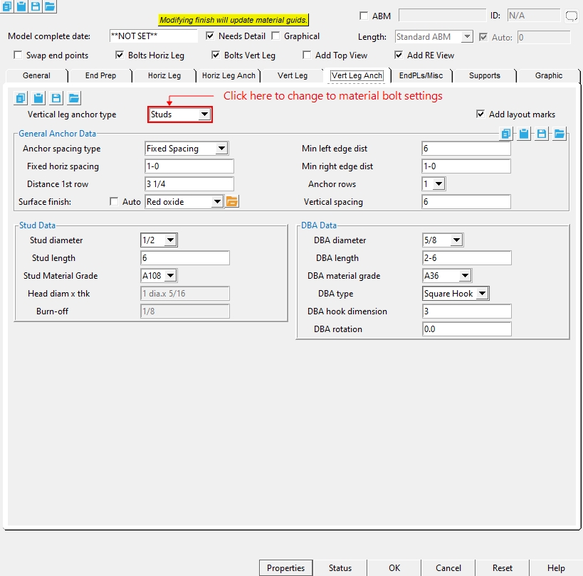
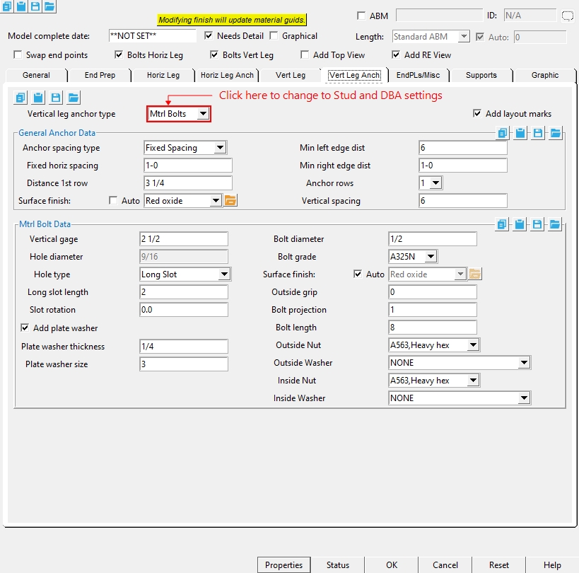
Vert Leg Anch Tab
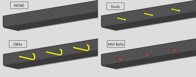
Vertical leg anchor type : NONE or Studs or DBAs or Mtrl Bolts.
Add layout marks :
![]() or
or ![]() . This is known as CNC Marks.
. This is known as CNC Marks.
If this box is checked (
General Anchor Data
Anchor spacing type : Fixed Spacing or Maximum Spacing.
Fixed Anchor Spacing Settings :
Fixed horiz spacing : Sets the exact distance between the anchors on the vertical leg. When Fixed spacing is set, you then set a minimum distance from the left edge, and right edge of the pour stop.
Min left edge dist : When the anchor spacing type is " Fixed Spacing ". The anchor that is nearest to the left end of the pour stop will be placed at least this distance away from the left-end workpoint of the pour stop.
Min right edge dist : When the anchor spacing type is " Fixed Spacing ". The anchor that is nearest to the right end of the pour stop will be placed at least this distance away from the right-end workpoint of the pour stop.
Maximum Anchor Spacing Settings :
Max horiz spacing : Sets the exact distance the first anchor is located from the left edge, and the first anchor from the right edge of the pour stop. This then uses the ' Max Horiz spacing ' to set the distance between holes equally.
Fixed left edge dist : When the anchor spacing type is " Maximum Spacing ". The anchor that is nearest to the left end of the pour stop will be placed this distance away from the left-end workpoint of the pour stop.
Fixed right edge dist : When the anchor spacing type is " Maximum Spacing ". The anchor that is nearest to the right end of the pour stop will be placed this distance away from the right-end workpoint of the pour stop.
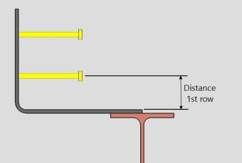
Distance 1st row : The vertical distance from the inside face of the pour stop's horizontal legs.
Surface finish : None or Sandblasted or Red oxide or Yellow zinc or Gray oxide or Blued steel or Galvanized or Duplex Coating or Undefined 1 or Undefined 2 or Undefined 3 or Red oxide 2 or Any user added surface finish. This affects the colors of 'Solid ' members on erection views in the Drawing Editor . This also sets the color when "Output material color " is set to 'Surface finish ' for a VRML Export or a DWG/DXF Export . The "Color " ( not "Surface finish ") sets the color of this material in Modeling .
| sand blasted | red oxide | yellow zinc | user surface finish 1 |
| gray oxide | blued steel | galvanized | user surface finish 2 |
To assign a different surface finish, you can drop-down the current surface finish and select the one you want, or you can press the "file cabinet" browse button (
Anchor rows : The number of anchor rows.
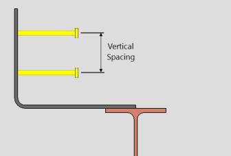
Vertical spacing : The vertical distance between anchor rows.
Stud Data
Stud diameter : The rod diameter of the shear stud or threaded stud.
Stud length : The distance between the two ends of the shear stud or threaded stud. The head is included in the length of a shear stud.
Stud Material Grade : A108 or A493 or etc. This is the grade of steel for the shear stud or threaded stud whose settings are defined on this window.
Setup: If the grade of steel you want is not shown in the list box (
Head diam x thik : (read-only) The diameter of the shear stud's head by the thickness of the head.
Burn- off :(read-only) the reduction in length of a weld stud, which occurs during the arc stud welding process.
DBA Data
DBA diameter : Any round bar " Section size " that is maintained in the local shape file .
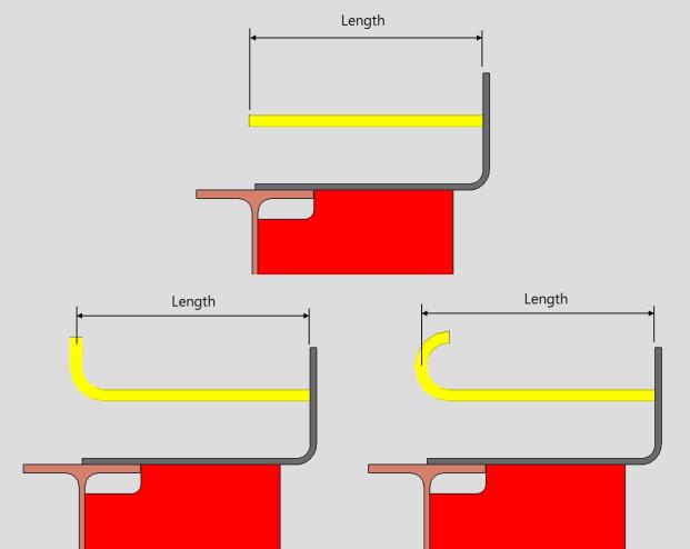
DBA length : The actual length when DBA when the " DBA Type " is ' Straight '. For DBAs with a " DBA Type " including ' Hook ', the actual unbent length of the DBA will be substantially larger than this " Length ." For DBAs with an " End operation " of ' Bend ', the actual unbent length of the DBA will be a bit larger than this " Length ."
DBA material grade : Any steel grade that is available at Home > Project Settings > Job > Round and Square Bar Grades can be selected here.
DBA type : Straight or Square Hook or J hook .

DBA hook dimension : The vertical dimension that the hook extends from the length of the DBA. Only applies when the ' DBA Type ' is set to Square Hook or J hook.
DBA rotation : The rotation of the DBA along the center of the round bar against the pour stop. Only applies when the ' DBA Type ' is set to Square Hook or J hook.
Mtrl Bolt Data
Vertical gage : The vertical distance from the bottom side of the pour stop to the 1st bolt row.
Hole diameter : The hole size that is reported here is calculated automatically based on the " Hole type " and the " Bolt diameter ."
Hole type : Standard round or Short slot or Oversized round or Long slot or Cope hole or Erection pin hole or Anchor bolt hole or Plug weld hole. For a more thorough explanation of each of these types, see " Hole type " on the Hole Edit window.
All hole types work together with the " Bolt diameter " to set the " Hole diameter ."
' Short slot ' sets the " Slot length " to be a particular length.
' Long slot ' allows the user to set the " Long Slot length ."
Long slot length : The distance (in the primary dimension " Units " or other units ) between the two points farthest from one another on the perimeter of a slot. This applies when the " Hole type " is ' Long slot '.
slot length 
Slot rotation : A positive or negative number from 90 to -90 degrees. This applies when the " Hole type " is ' Long slot ' or ' Short slot '. Slot rotations can be modeled to a precision of 0.1 degree.
when the hole group X axis
is horizontal (<==>)
when the hole group X axis
is vertical
Plate washer thickness : The thickness of the square plate or round plate washer.
t = thickness
Plate washer size : The width and length of the square plate washer.

Bolt diameter : The diameter (inches or mm) of the shank of the bolt. This field is directly linked to the " Bolt Diameter " that is set in the Horizontal Leg Hole Data, If either is changed the other updates.
diameter
Bolt grade : A325N or A325SC or A325X , etc. The bolt types that you can choose in the list box ( ![]() ) are the bolt types that are listed at Home > Project Settings > Job > Bolt Specifications .
This field is directly linked to the " Bolt type " that is set in the Horizontal Leg Hole Data, If either is changed the other updates.
) are the bolt types that are listed at Home > Project Settings > Job > Bolt Specifications .
This field is directly linked to the " Bolt type " that is set in the Horizontal Leg Hole Data, If either is changed the other updates.
Surface finish : None or Sandblasted or Red oxide or Yellow zinc or Gray oxide or Blued steel or Galvanized or Duplex Coating or Undefined 1 or Undefined 2 or Undefined 3 or Red oxide 2 or Any user added surface finish. This affects the colors of 'Solid ' members on erection views in the Drawing Editor . This also sets the color when "Output material color " is set to 'Surface finish ' for a VRML Export or a DWG/DXF Export . The "Color " ( not "Surface finish ") sets the color of this material in Modeling .
| sand blasted | red oxide | yellow zinc | user surface finish 1 |
| gray oxide | blued steel | galvanized | user surface finish 2 |
To assign a different surface finish, you can drop-down the current surface finish and select the one you want, or you can press the "file cabinet" browse button (
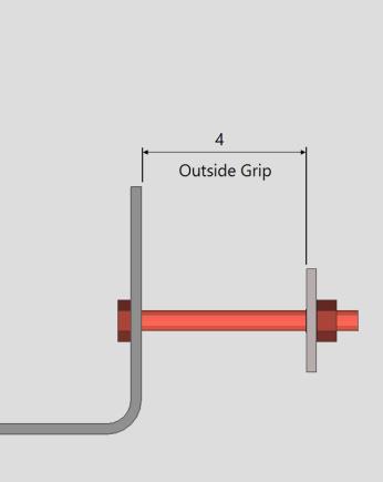
Outside grip : The distance between the outside face of pour stop and the outside washer or nut. Use this to set the location of the outside nut and washer.
Bolt projection : The distance between the Outside grip and the end of the bolt. Use this to set the location of the end of the bolt.
Bolt length : The distance from the inside of the bolt head to the end of the bolt shank. The bolt' s head thickness is not included in the calculation of bolt length because head thickness may vary among bolt manufacturers.
Outside Nut :NONE or A563, Heavy hex or A563-C, Heavy hex or A563-DH, Heavy hex or A194, Heavy hex.
heavy hex nut
Outside Washer : NONE or F436,Hardened or F436,Flat or F436,Bevel or F959,Direct tension indicator or A36,Square plate or A36,Round plate or A536-84,Hillside or A36,Material plate .
type shape BOM thickness bevel BVL " Bevel washers "
( Home > Project Settings > Job > Washer Settings )square
platePL " Nut washer thickness "
(see below)round
plateRPL " Nut washer thickness "
(see below)direct tension
indicatorDTI " Direct tension indicator "
( Home > Project Settings > Job > Washer Settings )hillside HLS - flat FL " Flat washers "
( Home > Project Settings > Job > Washer Settings )hardened HD " Hardened washers "
( Home > Project Settings > Job > Washer Settings )
Inside Nut : NONE or A563, Heavy hex or A563-C, Heavy hex or A563-DH, Heavy hex or A194, Heavy hex.
heavy hex nut
Inside Washer : NONE or F436,Hardened or F436,Flat or F436,Bevel or F959,Direct tension indicator or A36,Square plate or A36,Round plate or A536-84,Hillside or A36,Material plate .
type shape BOM thickness bevel BVL " Bevel washers "
( Home > Project Settings > Job > Washer Settings )square
platePL " Nut washer thickness "
(see below)round
plateRPL " Nut washer thickness "
(see below)direct tension
indicatorDTI " Direct tension indicator "
( Home > Project Settings > Job > Washer Settings )hillside HLS - flat FL " Flat washers "
( Home > Project Settings > Job > Washer Settings )hardened HD " Hardened washers "
( Home > Project Settings > Job > Washer Settings )
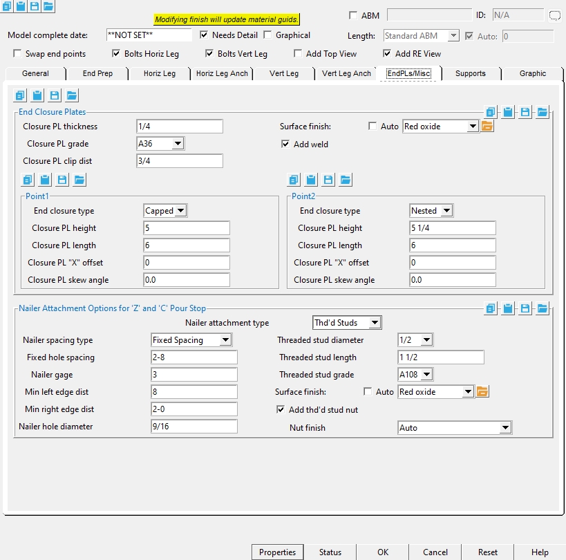
EndPls/Misc Tab
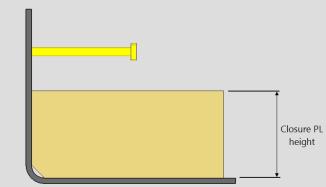
End Closure Plates
Closure PL thickness : The thickness of each of the closure plate. This is also the " Material thickness " of the rectangular plate that the closure plate is made of.
Closure PL grade : A36 or A572 or etc. This is the grade of steel for the closure plate. This is also the " Steel grade " of the rectangular plate that the closure plate is made of.
Setup: If the grade of steel you want is not shown on the list box (
Closure PL clip dist : A horizontal or vertical distance used to clip the inside corner of a nested closure plate at a 45 degree angle. A clip dimension of 0 keeps the inside corner square.
Note : This only applies when the 'End Closure Type' is set to 'Nested'.
Surface finish : None or Sandblasted or Red oxide or Yellow zinc or Gray oxide or Blued steel or Galvanized or Duplex Coating or Undefined 1 or Undefined 2 or Undefined 3 or Red oxide 2 or Any user added surface finish. This affects the colors of 'Solid ' members on erection views in the Drawing Editor . This also sets the color when "Output material color " is set to 'Surface finish ' for a VRML Export or a DWG/DXF Export . The "Color " ( not "Surface finish ") sets the color of this material in Modeling .
| sand blasted | red oxide | yellow zinc | user surface finish 1 |
| gray oxide | blued steel | galvanized | user surface finish 2 |
To assign a different surface finish, you can drop-down the current surface finish and select the one you want, or you can press the "file cabinet" browse button (
If this box is checked (
If this box is unchecked (
Point1 / Point2
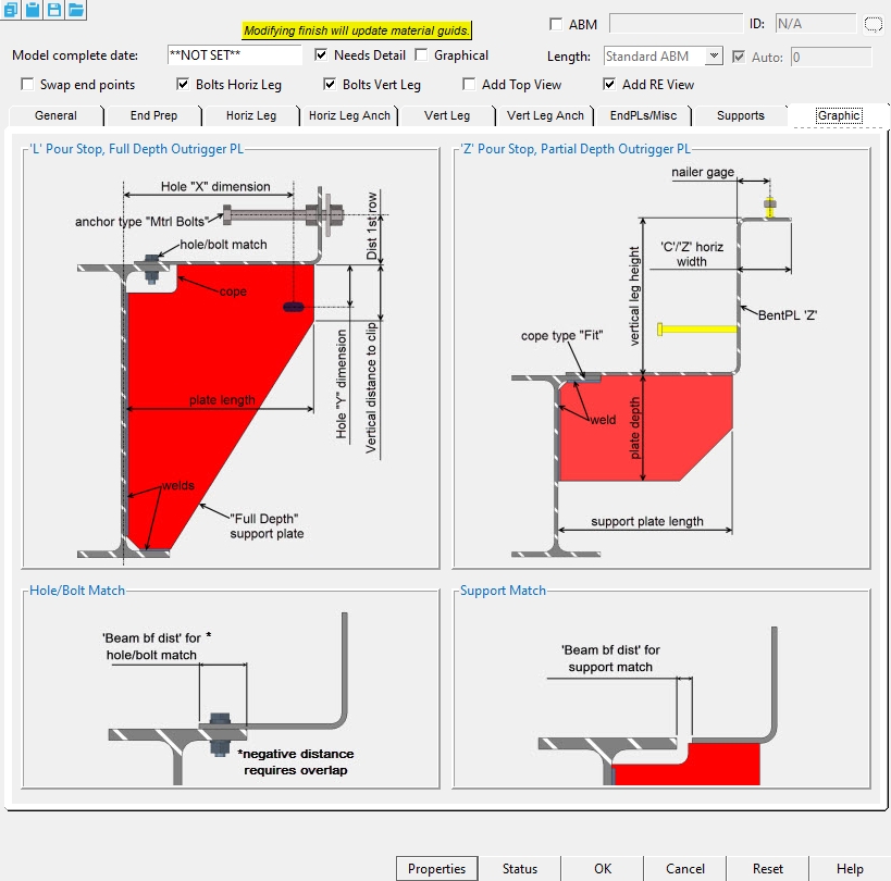
End closure type : None or Capped or Nested
None : The end that this is selected on will not include a closure plate.
Capped : The closure plate is placed on the outside of the pour stop main material.
Nested : The closure plate is placed flush with the outside of the pour stop main material.
Closure PL height : The vertical dimension from the bottom of the plate to the top of the plate.
Closure PL length : The horizontal distance from end to end of the plate.
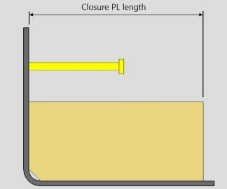
Closure PL "X" offset : A distance the closure plate is moved from the end of the pour stop main material end.
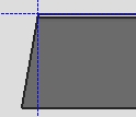
Closure PL skew angle : Any positive or negative (-) angle measured in degrees ( 8 to -80 ). A positive value rotates the plate in a clockwise direction.
Nailer Attachment Options for 'Z' and 'C' Pour Stop
Nailer attachment type : None or Nailer Holes or Thd'd Studs.
Nailer Holes : Places 'Nailer Holes' in the top leg of the 'C' shape or 'Z' shape pour stop.
Thd'd Studs : Attaches threaded studs to the top leg of the 'C' shape or 'Z' shape pour stop.
Nailer spacing type : NONE or Fixed Spacing or Maximum Spacing.
NONE : Means there are no holes added to the pour stop horizontal leg.
Fixed Spacing: Sets the exact distance between the holes in the horizontal leg. When Fixed spacing is set, you then set a minimum distance from the left edge, and right edge of the pour stop and the Fixed Hole Spacing.
Maximum Spacing : Sets the exact distance the first hole is located from the left edge, and right edge of the pour stop. This then uses the Max Hole spacing to set the distance between holes equally.
Fixed hole spacing : A set center-to-center distance between holes along the length of the pour stop member. (Only applicable when the Hole spacing type is set to Fixed Spacing).
Min left edge dist : When the hole spacing type is " Fixed Spacing ". The hole that is nearest to the left end of the pour stop will be placed at least this distance away from the left-end workpoint of the pour stop.
Min right edge dist :When the hole spacing type is " Fixed Spacing ". The hole that is nearest to the right end of the pour stop will be placed at least this distance away from the right-end workpoint of the pour stop.
Max hole spacing :A maximum center-to-center distance between holes along the length of the pour stop member. (Only applicable when the Hole spacing type is set to Maximum Spacing)
Fixed left edge dist : When the hole spacing type is " Maximum Spacing ". The hole that is nearest to the left end of the pour stop will be placed this distance away from the left-end workpoint of the pour stop.
Fixed right edge dist : When the hole spacing type is " Maximum Spacing ". The hole that is nearest to the right end of the pour stop will be placed this distance away from the right-end workpoint of the pour stop.
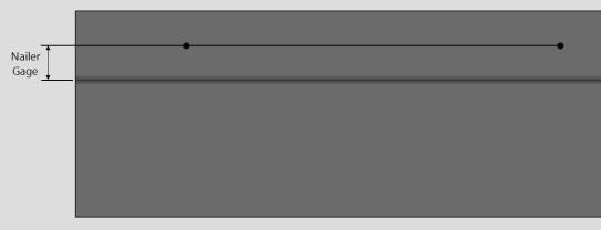
Nailer gage : The distance from the inside face of vertical leg to the nailer holes on the top leg.
Nailer hole diameter : The hole size that is placed in the 'C' or 'Z' horizontal leg.
Threaded stud diameter : The rod diameter of the Threaded stud.
Threaded stud length : The distance between the two ends of the threaded stud. The head is included in the length of a shear stud.
Threaded stud grade : A108 or A493 or etc. This is the grade of steel for the shear stud or threaded stud whose settings are defined on this window.
Setup: If the grade of steel you want is not shown in the list box (
Surface finish :None or Sandblasted or Red oxide or Yellow zinc or Gray oxide or Blued steel or Galvanized or Duplex Coating or Undefined 1 or Undefined 2 or Undefined 3 or Red oxide 2 or Any user added surface finish. This affects the colors of 'Solid ' members on erection views in the Drawing Editor . This also sets the color when "Output material color " is set to 'Surface finish ' for a VRML Export or a DWG/DXF Export . The "Color " ( not "Surface finish ") sets the color of this material in Modeling .
| sand blasted | red oxide | yellow zinc | user surface finish 1 |
| gray oxide | blued steel | galvanized | user surface finish 2 |
To assign a different surface finish, you can drop-down the current surface finish and select the one you want, or you can press the "file cabinet" browse button (
If this box is checked (
If the box is not checked (
Nut finish : Auto or Black or Mechanically galvanized or Hot dipped galvanized.
Supports Tab
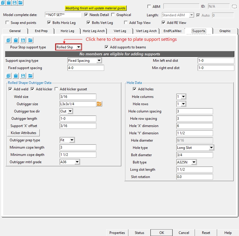
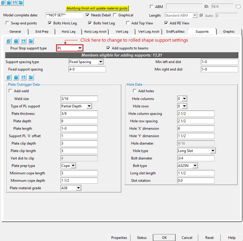
Pour Stop support type : PL or Rolled Shp.
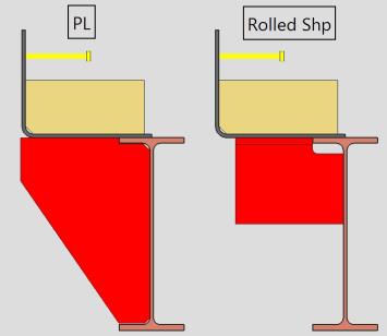
PL : Generates plate outrigger material on the beam to support the pour stop.
Rolled Shp : Generates outrigger materials out of wide flange, channel, angle, or WTee on the beam to support the pour stop.
If this box is checked (
If the box is not checked (
Support spacing type : Fixed Spacing or Maximum Spacing or Variable Spa.
Fixed Spacing: Sets the exact distance between the supports in the vertical leg. When Fixed spacing is set, you then set a minimum distance from the left edge, and right edge of the pour stop and the Fixed Support Spacing.
Maximum Spacing : Sets the exact distance the first support is located from the left edge, and right edge of the pour stop. This then uses the Max Support spacing to set the distance between holes equally.
Variable Spa : Lets you type in the spacing values between each support.
Fixed Spacing Options
Fixed support spacing : A set center-to-center distance between supports along the length of the pour stop member. (Only applicable when the support spacing type is set to Fixed Spacing)
Min left end dist :When the support spacing type is " Fixed Spacing ". The support that is nearest to the left end of the pour stop will be placed at least this distance away from the left-end workpoint of the pour stop.
Min right end dist : When the support spacing type is " Fixed Spacing ". The support that is nearest to the right end of the pour stop will be placed at least this distance away from the right-end workpoint of the pour stop.
Maximum Spacing Settings :
Max support spacing : A maximum center-to-center distance between supports along the length of the pour stop member. (Only applicable when the support spacing type is set to Maximum Spacing)
Fixed left edge dist : When the support spacing type is " Maximum Spacing ". The support that is nearest to the left end of the pour stop will be placed this distance away from the left-end workpoint of the pour stop.
Fixed right edge dist : When the support spacing type is " Maximum Spacing ". The support that is nearest to the right end of the pour stop will be placed this distance away from the right-end workpoint of the pour stop.
Variable Spacing Settings :
Variable support spacing : A distance between the support spacings. Use commas to signify a new spacing for your supports. The spacing starts from Point1 towards Point2. The spacing is from the leftside face to the next left side face of the supports
Example : Spacing can be filled out with commas — like 12,18,18,18,12 — which will generate the first support 12 inches from the Point1 and then have three 18-inch spaces, then one last 12-inch space. You can achieve the same result by using an @; type in 12,3@18,12 to achieve the same result.
Rolled Shape Outrigger Data
If this box is checked (
If this box is unchecked (
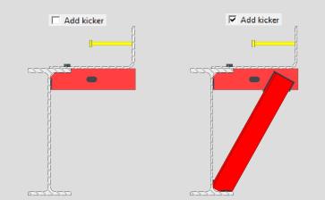
Weld size : The fillet weld size for welding the kicker angle to the supporting materials.
Outrigger size : Any Angle or Wide Flange or WTee or Channel " Section size " that is maintained in the local shape file.
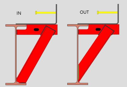
Outrigger toe dir : Out or In. This option applies when the outrigger's " Section size " is channel or single angle material.
' In ' points the toe of the angle (toes of the channel) toward you if you are facing the near side of the material in an elevation view.
' Out ' points the leg (or toes) away from you if you are facing the near side of the material in an elevation view.
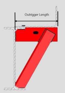
Outrigger length : Sets the length of the outrigger from the face of supporting member.
Support 'X' offset : Sets the offset of the Outrigger and supports along the length of the member line.
Outrigger prep type : Cope or Fit or Min or None.
Cope : copes the outrigger around the beam with the minimum cope size set from the settings below for the ' minimum cope length' and ' minimum cope depth. '
Fit : fits the outrigger to the beam flange with a minimum clearance between the two and clips the outrigger corner at the beam's K-distance radius.
Min : copes the outrigger around the beam following the minimum settings below for the ' minimum cope length' and ' minimum cope depth. Incorrect values set here can result in material clashing.
None : Does not apply any fit operations to the outrigger material. The outrigger material will clash with the supporting beam material.
Minimum cope length : The minimum distance that the outrigger uses when determining the cope length parallel to the flange. This only applies when the outrigger prep type is set to Cope.
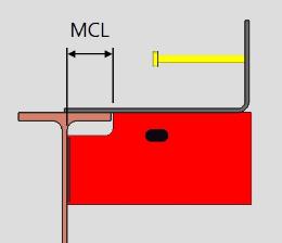
MCL = Minimum Cope Length
Minimum cope depth : The distance that the beam-side, top of the outrigger will be coped parallel to the depth of the beam. This only applies when the outrigger prep type is set to Cope.
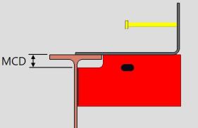
MCD = Minimum Cope Depth
Plate Outrigger Data
If this box is checked (
If this box is unchecked (
Weld size : The fillet weld size for welding the outrigger to the supporting member.
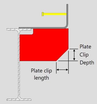
Type of PL support : Full Depth or Partial Depth.
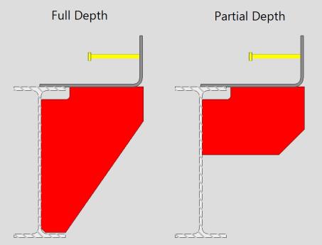
Full Depth : extends the bottom edge of each plate outrigger to the bottom flange of the beam.
Partial Depth : extends the bottom edge of each plate outrigger to the ' Plate depth ' , which is measured from the top flange of the beam.
Plate thickness :The thickness of this outrigger plate material.
To enter gage plate: Type in the ' gage number' followed by ' ga ' (example: ' 4ga ' is rewritten as ' 4GA ' when you Tab out of the field). Right-click tells you the stored thickness (based on industry standards), from which the weight of the gage plate is calculated. Allowable gages are any whole number from 3 to 38 .
Thickness precision: You can enter a plate " Material thickness " that is more precise than the " Dimension precision " that is set at Home > Project Settings > Fabricator > Detailing > Drawing Presentaton . For example, if you enter ' 5/32 ' and the " Dimension precision " is ' 1/16 ', the thickness of the plate will be ' 5/32 '. The thickness you enter will be reflected in the " Description " and will propagate to the bill of material, reports, etc. The setup option to " Round flat plate values " does not affect this. Be aware that the Ruler measures to whatever the " Dimension precision " is set to, which means that the plate's measured thickness may not exactly match its actual thickness.
Plate depth :The value that is entered here sets the depth of the plate outriggers. On the Rectangular Plate Material window, this will be the " Material Width " of each of the plates. This option only applies when 'Type of PL support' is set to Partial Depth.
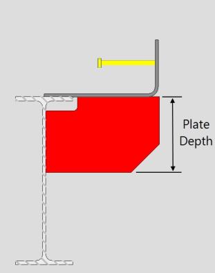
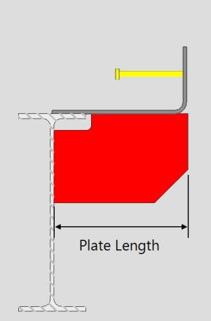
Plate length : The value that is entered here sets the length of the plate outriggers. On the Rectangular Plate Material window, this will be the " Order Length" of each of the plates.
Support PL 'X' offset : Sets the offset of the Outrigger and supports along the length of the member line.
Vert dist to clip : The distance from the bottom of the pour stop main material to where the clip begins.
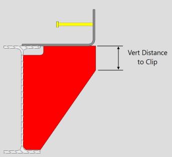
Plate prep type : Cope or Fit.
Cope : copes the outrigger around the beam with the minimum cope size set from the settings below for the ' minimum cope length' and ' minimum cope depth. '
Fit : fits the outrigger to the beam flange with a minimum clearance between the two and clips the outrigger corner at the beam's K-distance radius.
Minimum cope length : The minimum distance that the outrigger uses when determining the cope length parallel to the flange. This only applies when the outrigger prep type is set to Cope.
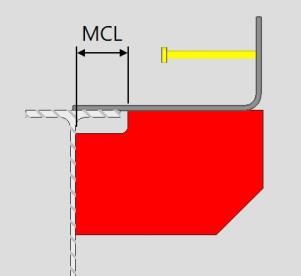
MCL = Minimum Cope Length
Minimum cope depth : The distance that the beam-side, top of the outrigger will be coped parallel to the depth of the beam. This only applies when the outrigger prep type is set to Cope
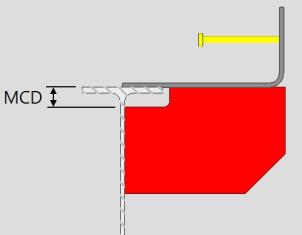
MCD = Minimum Cope Depth
The distance that the beam-side, top of the outrigger will be coped parallel to the depth of the beam. This only applies when the outrigger prep type is set to Cope.
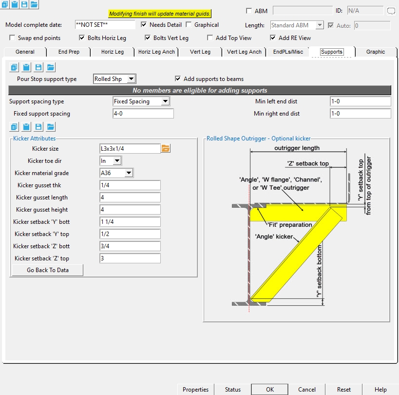
Kicker Attributes
Kicker size : Any Angle " Section size " that is maintained in the local shape file.
Kicker Material Grade : A36 or A572-50 or A588.
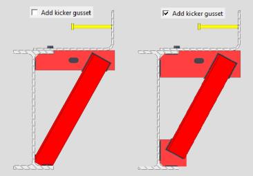
Kicker gusset thk : The thickness of the gusset plate.
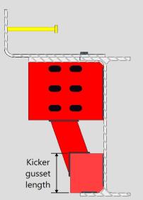
Kicker gusset length : The vertical distance of the gusset plate.
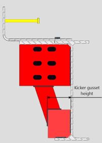
Kicker gusset height : The horizontal distance of the gusset plate.
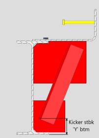
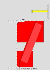
Kicker setback 'Y' bott : The vertical distance the kicker angle is setback from the bottom flange of the supporting member.
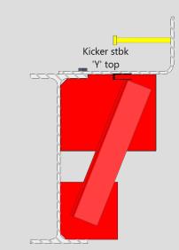
Kicker setback 'Y' top : The vertical distance the kicker angle is setback from the top of the outrigger.
Kicker setback 'Z' bott : The horizontal distance the kicker angle is setback from the center of the supporting beam.
Kicker setback 'Z' top :The horizontal distance the kicker angle is setback from the end of the outrigger.

Hole Data
If this box is checked (
If this box is unchecked (
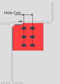
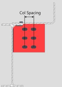
Hole columns :0 or 1 or 2. The number (count) of columns of holes.
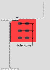
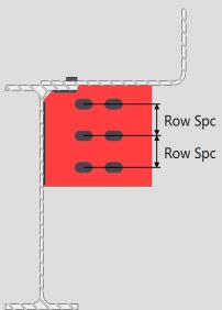
Hole rows : 0 or 1 or 2 or 3 or 4. The number (count) of rows of holes.
Hole column spacing : The distance between adjacent columns of holes. This distance is typically measured horizontally, parallel with the " Outrigger Length " dimension.
Hole row spacing : The distance between adjacent rows of holes. This distance is typically measured vertically, perpendicular with the " Outrigger Length " dimension.
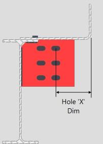
Hole 'X' dimension : The distance from the vertical leg of the pour stop to the first column of holes in the support.
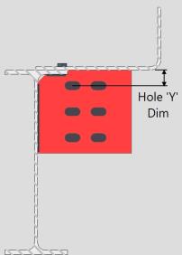
Hole 'Y' dimension : The distance from the top flange of the supporting member to the first row of holes in the support.
Hole diameter : (read only) The hole size that is reported here is calculated automatically based on the " Hole type " and the " Bolt diameter ."
Hole type : Standard round or Short slot or Oversized round or Long slot or Cope hole or Erection pin hole or Anchor bolt hole or Plug weld hole. For a more thorough explanation of each of these types, see " Hole type " on the Hole Edit window.
All hole types work together with the " Bolt diameter " to set the " Hole diameter ."
' Short slot ' sets the " Slot length " to be a particular length.
' Long slot ' allows the user to set the " Long Slot length ."
Bolt diameter : The diameter (inches or mm) of the shank of the bolt.
diameter
Bolt type :A325N or A325SC or A325X , etc. The bolt types that you can choose in the list box ( ![]() ) are the bolt types that are listed at Home > Project Settings > Job > Bolt Specifications .
) are the bolt types that are listed at Home > Project Settings > Job > Bolt Specifications .
Long slot length : The distance (in the primary dimension " Units " or other units ) between the two points farthest from one another on the perimeter of a slot. This applies when the " Hole type " is ' Long slot '.
slot length
Slot rotation : A positive or negative number from 90 to -90 degrees. This applies when the " Hole type " is ' Long slot ' or ' Short slot '. Slot rotations can be modeled to a precision of 0.1 degree.
when the hole group X axis
is horizontal (<==>)
when the hole group X axis
is vertical
1 . Invoke Pour Stop by clicking the Pour Stop icon, which is pictured above. The icon can be found on the Members page > Steel section.
Alternative : Pour Stop can also be invoked using the Find Tool by searching the command name and clicking the Pour Stop icon, which is pictured above.
2 .Locate- Repeat -Return mouse bindings become active along with various Locate options.
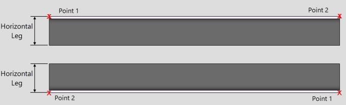
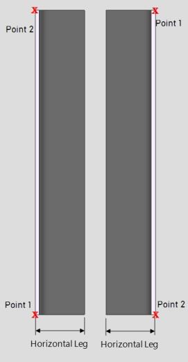
Note : The end points you are selecting are at the heel of the bent plate or angle material. The direction the points are selected affects the direction of the horizontal leg. In a plan view, if the points are selected left to right, the horizontal leg toes towards the bottom of the screen. If the points are selected bottom to top, the horizontal leg toes to the right of the screen.
3 . Locate the first point of the pour stop. The first point selected will be your point1 (similar to the left end for other members).
4 . Locate the second point of the pour stop. The second point select will be your point2 (similar to the right end for other members). This second point sets the length of the member.
5 . The Pour Stop window opens.
5a : Make the appropriate setting changes in the Pour Stop edit window, press " OK " to go to step 6 .
6 . The Pour Stop member is added. Locate - Repeat - Return mouse bindings become active. Do one (1) of the following:
Alternative 1 : Left-click ( Locate ) to repeat steps 2-5 above.
Alternative 2 : Middle-click ( Repeat ) to cause an exact duplicate of the pour stop to be drawn over wherever the point location target (
) is at.
Alternative 3 : Right-click ( Return ) to get out of the tool and bring back whatever mouse bindings were active before you invoked Pour Stop.
-
The order the points are selected affects the toe direction of the horizontal leg. In a plan view, if the points are selected left to right, the horizontal leg toes towards the bottom of the screen. If the points are selected bottom to top, the horizontal leg toes to the right of the screen.
-
Horizontal Example :
-
Vertical Example :
-