AISC Verification Problem Example II.A-18
- Example
- Related
Problem Statement
This document presents a comparative study between the published American Institute of Steel Construction (AISC) Design Examples Version 16.0 and the results generated by SDS2 version 2025.01 connection software for Example II.A-18. The central problem statement is to verify the available strength of single plate shear tab of a beam to girder web connection. This connection involves an ASTM A992 W18×35 beam and an ASTM A992 W21×62 girder supporting beam end reactions of RD = 6.5 kips and RL = 20 kips, using an ASTM A572/A572M Grade 50 shear tab. The connection is shown in Figure 1.
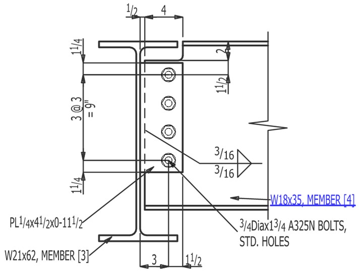
Figure 1. Example II.A-18 elevation view
Connection design report output from SDS2 for this connection:
Note: To view the 3D model (U3D) of the structural joint in the PDF files, open the PDF using Bluebeam or Adobe Acrobat Reader.
Validation Method
The connection as shown in the AISC design example II.A-18 (see reference 1) was modeled in SDS2 and a connection design report was generated for both the ASD and LRFD design methods.
The core of this report features a comparison table for each connection limit state, showcasing the calculated capacities from both SDS2 and AISC. The order of the limit state table generally mirrors the sequence in which it was presented in the AISC example problem. This table also highlights the percent difference (% Δ) between these calculated values, providing a clear measure of any discrepancy, if any.
To further enhance understanding, this report includes relevant notes that discuss any differences or assumptions made during the calculation process. In certain cases where AISC did not calculate a connection capacity for a limit state, the connection capacity was back calculated based on the limit state values and documentation for this calculation is provided in the notes. The goal of this comparative study is to evaluate the precision and efficiency of the SDS2 connection design software in contrast to the AISC Design Examples and serves as a guide for better understanding and application of these two design calculations.
Comparison
Comparisons of the limit state checks are presented in Table 1 for ASD and Table 2 for LRFD. The limit state checks and calculated values aligned well between the published AISC Design Example document and the calculation generated by SDS2. The minor differences in calculated values, except where noted, were a result of rounding differences.
|
Table 1. Capacity comparison table for ASD |
||||
|
Limit state (ASD) |
SDS2 Capacity |
AISC Capacity |
%Δ |
Notes |
|---|---|---|---|---|
|
Shear rupture of plate |
39.0 kips |
39.0 kips |
0.0% |
|
|
Block shear rupture of plate |
43.6 kips |
|||
|
Rupture of weld to column |
- |
|||
|
Bolt shear of web bolts |
11.9 kips / bolt |
11.9 kips / bolt |
0.0% |
|
|
Coefficient for eccentrically load bolt group, C |
3.56 |
3.54 |
0.6% |
|
|
Bolt bearing on plate |
14.63 kips / bolt |
8.23 kips / bolt |
0.0% |
|
|
Bolt tearout on plate at edge bolt |
8.23 kips / bolt |
|||
|
Bolt bearing and tearout on plate at non-edge bolts |
14.6 kips / bolt |
14.6 kips / bolt |
0.0% |
|
|
Bolt bearing on web |
17.6 kips / bolt |
12.8 kips / bolt |
0.0% |
|
|
Bolt tearout on web at edge bolt |
12.8 kips / bolt |
|||
|
Bolt bearing and tearout on web at non-edge bolts |
17.6 kips / bolt |
17.6 kips / bolt |
0.0% |
|
|
Bolt group shear of web bolts |
42.5 kips |
- |
- |
|
|
Bolt group bearing on plate |
44.0 kips |
- |
- |
|
|
Bolt group bearing on web |
47.7 kips |
- |
- |
|
|
Shear transfer at bolts |
42.5 kips |
38.9 kips |
8.5% |
|
|
Block shear rupture of beam web |
63.6 kips |
58.7 kips |
7.7% |
|
|
Flexure of coped beam |
169.2 kips |
- |
- |
|
|
Rupture of weld to girder web |
- |
OK |
- |
|
|
Shear of support |
179.4 kips |
- |
- |
|
|
Shear yielding of plate |
57.5 kips |
- |
- |
|
|
Flexure of plate |
165.7 kips |
- |
- |
|
|
Shear rupture of beam web |
71.4 kips |
- |
- |
|
|
Shear yielding of beam web |
94.2 kips |
- |
- |
|
|
Connection capacity |
39.0 kips |
38.9 kips |
0.3% |
|
|
Table 2. Capacity comparison table for LRFD |
||||
|
Limit state (LRFD) |
SDS2 Capacity |
AISC Capacity |
%Δ |
Notes |
|---|---|---|---|---|
|
Shear rupture of plate |
58.5 kips |
58.5 kips |
0.0% |
|
|
Block shear rupture of plate |
65.4 kips |
|||
|
Rupture of weld to column |
- |
|||
|
Bolt shear of web bolts |
17.9 kips / bolt |
17.9 kips / bolt |
0.0% |
|
|
Coefficient for eccentrically load bolt group, C |
3.56 |
3.54 |
0.6% |
|
|
Bolt bearing on plate |
21.9 kips / bolt |
12.4 kips / bolt |
-0.5% |
|
|
Bolt tearout on plate at edge bolt |
12.30 kips / bolt |
|||
|
Bolt bearing and tearout on plate at non-edge bolts |
21.9 kips / bolt |
22.0 kips / bolt |
-0.5% |
|
|
Bolt bearing on web |
26.3 kips / bolt |
19.2 kips / bolt |
0.0% |
|
|
Bolt tearout on web at edge bolt |
19.2 kips / bolt |
|||
|
Bolt bearing and tearout on web at non-edge bolts |
26.3 kips / bolt |
26.3 kips / bolt |
0.0% |
|
|
Bolt group shear of web bolts |
63.7 kips |
- |
- |
|
|
Bolt group bearing on plate |
66.0 kips |
- |
- |
|
|
Bolt group bearing on web |
71.6 kips |
- |
- |
|
|
Shear transfer at bolts |
63.7 kips |
58.5 kips |
8.2% |
|
|
Block shear rupture of beam web |
95.4 kips |
88.2 kips |
7.5% |
|
|
Flexure of coped beam |
254.3 kips |
- |
- |
|
|
Rupture of weld to girder web |
- |
OK |
- |
|
|
Shear of support |
269.1 kips |
- |
- |
|
|
Shear yielding of plate |
86.3 kips |
- |
- |
|
|
Flexure of plate |
249.0 kips |
- |
- |
|
|
Shear rupture of beam web |
107.1 kips |
- |
- |
|
|
Shear yielding of beam web |
141.3 kips |
- |
- |
|
|
Connection capacity |
58.5 kips |
58.5 kips |
0.0% |
|
Table Notes
Note 1: AISC checks shear rupture, block shear rupture, and weld shear in one lookup value from Manual Table 10-10a.
Note 2: SDS2 shows the weld is sized to develop the full strength of the plate.
Note 3: The AISC C value was back calculated as: C/n * n = 0.885 * 4 = 3.54.
Note 4: AISC checks bolt bearing and tearout strength in one lookup value from Manual Table 10-10b.
Note 5: AISC does not calculate this individual limit state per bolt group.
Note 6: AISC designs the bolt bearing/tearout for eccentricity. SDS2 designs the bearing/tearout limit states for a concentrically applied load and bolt shear for eccentricity since this connection meets the requirements of the conventional configuration per AISC 16th Edition Steel Construction Manual pg. 10-49. For the conventional configuration, the plate bearing and tearout can be checked assuming the reaction is applied concentrically.
Note 7: AISC checks top edge, center, and bottom edge looked up from Manual Table 10-1c. The footnote in Table 10-1C notes that the tabulated values account for a 1/4" reduction in leh to account for possible underrun in beam length. The difference in this calculated value is due to AISC is using leh of 2.25" where SDS2 is using the full 2.5".
Note 8: AISC only notes that this limit state does not govern.
Note 9: SDS2 checks the weld size is 5/8 * (tab thickness) and shows the weld is capable of developing the strength of the plate. AISC checks the minimum support thickness to match the shear rupture strength of the supporting beam web. AISC does not check that that the weld is capable of developing the strength of the plate.
Note 10: Not checked by AISC, but it does check that the weld can develop strength of web. AISC checks shear yield and shear rupture of the supporting member web. Although not shown in AISC Ex. II.A-18, rupture of the supporting member is checked in AISC Ex. II.A-17B (page IIA-184) and it is noted that shear yielding doesn't control.
References
-
AISC Committee on Manuals, Companion to the AISC Steel Construction Manual Volume 1: Design Examples, Version 16.0, American Institute of Steel Construction, 2023, https://www.aisc.org/publications/steel-construction-manual-resources/16th-ed-steel-construction-manual/manual-companion-for-16th-edition/.

