AISC Verification Problem Example II.B-1
- Example
- Related
Problem Statement
This document presents a comparative study between the published American Institute of Steel Construction (AISC) Design Examples Version 16.0 and the results generated by SDS2 version 2025.01 connection software for Example II.B-1. The central problem statement is to verify the available strength of a bolted flange-plated fully restrained moment shear tab beam to column flange connection. This connection involves an ASTM A992 W18×50 beam and an ASTM A992 W14×99 column with end reactions of VD = 7 kips, VL = 21 kips, MD = 42 kip-ft, and ML = 126 kip-ft, using ASTM A572 Grade 50 shear and flange plates. The connection is shown in Figure 1 and Figure 2.
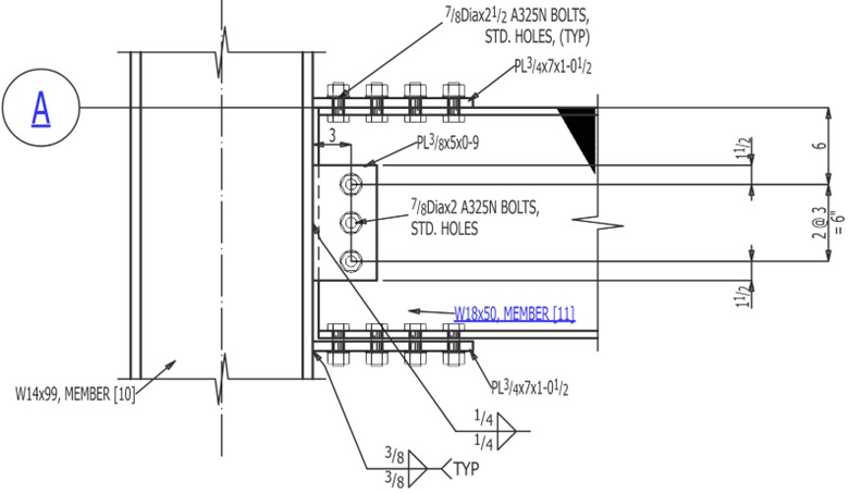
Figure 1. Example II.B-1 elevation view
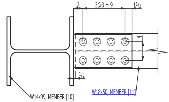
Figure 2. Example II.B-1 section A
Connection design report output from SDS2 for this connection:
Note: To view the 3D model (U3D) of the structural joint in the PDF files, open the PDF using Bluebeam or Adobe Acrobat Reader.
Validation Method
The connection as shown in the AISC design example II.B-1 (see reference 1) was modeled in SDS2 and a connection design report was generated for both the ASD and LRFD design methods.
The core of this report features a comparison table for each connection limit state, showcasing the calculated capacities from both SDS2 and AISC. The order of the limit state table generally mirrors the sequence in which it was presented in the AISC example problem. This table also highlights the percent difference (% Δ) between these calculated values, providing a clear measure of any discrepancy, if any.
To further enhance understanding, this report includes relevant notes that discuss any differences or assumptions made during the calculation process. In certain cases where AISC did not calculate a connection capacity for a limit state, the connection capacity was back calculated based on the limit state values and documentation for this calculation is provided in the notes. The goal of this comparative study is to evaluate the precision and efficiency of the SDS2 connection design software in contrast to the AISC Design Examples and serves as a guide for better understanding and application of these two design calculations.
Comparison
Comparisons of the limit state checks are presented in Table 1 for ASD and Table 2 for LRFD. The limit state checks and calculated values aligned well between the published AISC Design Example document and the calculation generated by SDS2. The minor differences in calculated values, except where noted, were a result of rounding differences.
|
Table 1. Capacity comparison table for ASD |
||||
|
Limit state (ASD) |
SDS2 Capacity |
AISC Capacity |
%Δ |
Notes |
|---|---|---|---|---|
|
Flexural rupture of beam |
211 kip-ft |
211 kip-ft |
0.0% |
|
|
Bolt shear of web bolts |
16.2 kips / bolt |
16.2 kips / bolt |
0.0% |
|
|
Bolt bearing on web plate |
25.6 kips / bolt |
25.6 kips / bolt |
0.0% |
|
|
Bolt tearout on web plate at non-edge bolt |
30.2 kips / bolt |
30.2 kips / bolt |
0.0% |
|
|
Bolt tearout on web plate at edge bolt |
15.1 kips / bolt |
15.1 kips / bolt |
0.0% |
|
|
Bolt bearing on beam web |
24.2 kips / bolt |
24.3 kips / bolt |
-0.4% |
|
|
Bolt tearout on beam web |
28.6 kips / bolt |
28.5 kips / bolt |
0.3% |
|
|
Bolt group shear of web bolts |
48.7 kips |
- |
- |
|
|
Bolt group bearing on plate |
47.6 kips |
- |
- |
|
|
Bolt group bearing on beam web |
48.7 kips |
- |
- |
|
|
Shear transfer at web bolts |
47.6 kips |
47.5 kips |
0.2% |
|
|
Shear yielding of web plate |
67.5 kips |
67.3 kips |
0.3% |
|
|
Shear rupture of web plate |
43.9 kips |
43.9 kips |
0.0% |
|
|
Block shear rupture of web plate |
54.5 kips |
54.9 kips |
-0.7% |
|
|
Weld shear of web plate to column flange |
- |
66.8 kips |
- |
|
|
Column flange rupture at welds (shear of support) |
274 kips |
273 kips |
0.3% |
|
|
Bolt shear of flange bolts |
16.2 kips / bolt |
16.2 kips / bolt |
0.0% |
|
|
Bolt bearing on flange plate |
51.2 kips / bolt |
51.0 kips / bolt |
0.4% |
|
|
Bolt tearout on flange plate at non-edge bolt |
60.3 kips / bolt |
60.5 kips / bolt |
-0.3% |
|
|
Bolt tearout on flange plate at edge bolt |
30.2 kips / bolt |
30.2 kips / bolt |
0.0% |
|
|
Bolt bearing on flange |
38.9 kips / bolt |
38.9 kips / bolt |
0.0% |
|
|
Bolt tearout on beam flange at non-edge bolt |
45.8 kips / bolt |
45.8 kips / bolt |
0.0% |
|
|
Bolt tearout on beam flange at edge bolt |
23.8 kips / bolt |
22.9 kips / bolt |
3.8% |
|
|
Bolt group shear of flange bolts |
194.8 kip-ft |
- |
- |
|
|
Bolt group bearing on flange plate |
194.8 kip-ft |
- |
- |
|
|
Bolt group bearing on beam flange |
194.8 kip-ft |
- |
- |
|
|
Bolt group strength at flange plate (limit state) |
130 kips |
130 kips |
0.0% |
|
|
Bolt group strength at flange plate (moment) |
195 kip-ft |
195 kip-ft |
0.0% |
|
|
Tension yield of flange plate (limit state) |
122 kips |
122 kips |
0.0% |
|
|
Tension yield of flange plate (moment) |
190 kip-ft |
191 kip-ft |
-0.3% |
|
|
Block shear rupture of flange plate (limit state) |
200 kips |
200 kips |
0.0% |
|
|
Block shear rupture of flange plate (moment) |
312 kip-ft |
313 kip-ft |
-0.2% |
|
|
Block shear rupture of beam flange (limit state) |
203 kips |
197 kips |
3.0% |
|
|
Block shear rupture of beam flange (moment) |
295 kip-ft |
296 kip-ft |
-0.3% |
|
|
Rupture of flange plate weld |
182.7 kip-ft |
181.9 kip-ft |
0.4% |
|
|
Compression of flange plate (limit state) |
157 kips |
157 kips |
0.0% |
|
|
Compression of flange plate (moment) |
245.3 kip-ft |
245.3 kip-ft |
0.0% |
|
|
Column flange local bending (limit state) |
114 kips |
114 kips |
0.0% |
|
|
Column web local yielding (limit state) |
124 kips |
124 kips |
0.0% |
|
|
Strength of column flange (moment) |
177.9 kip-ft |
178.1 kip-ft |
-0.1% |
|
|
Column web local crippling (limit state) |
155 kips |
155 kips |
0.0% |
|
|
Column web local crippling (moment) |
241.9 kip-ft |
242.2 kip-ft |
-0.1% |
|
|
Panel zone shear of column web |
193.3 kip-ft |
- |
- |
|
|
Shear yielding of beam web |
127.8 kips |
- |
- |
|
|
Flange plate width to thickness ratio |
0.149 |
- |
- |
|
|
Connection capacity (shear) |
43.9 kips |
43.9 kips |
0.0% |
|
|
Connection capacity (moment) |
177.9 kip-ft |
178.1 kip-ft |
-0.1% |
|
|
Table 2. Capacity comparison table for LRFD |
||||
|
Limit state (LRFD) |
SDS2 Capacity |
AISC Capacity |
%Δ |
Notes |
|---|---|---|---|---|
|
Flexural rupture of beam |
318 kip-ft |
318 kip-ft |
0.0% |
|
|
Bolt shear of web bolts |
24.4 kips / bolt |
24.3 kips / bolt |
0.2% |
|
|
Bolt bearing on web plate |
38.4 kips / bolt |
38.4 kips / bolt |
0.0% |
|
|
Bolt tearout on web plate at non-edge bolt |
45.2 kips / bolt |
45.2 kips / bolt |
0.0% |
|
|
Bolt tearout on web plate at edge bolt |
22.6 kips / bolt |
22.6 kips / bolt |
0.0% |
|
|
Bolt bearing on beam web |
36.3 kips / bolt |
36.4 kips / bolt |
-0.3% |
|
|
Bolt tearout on beam web |
42.8 kips / bolt |
42.8 kips / bolt |
0.0% |
|
|
Bolt group shear of web bolts |
73.1 kips |
- |
- |
|
|
Bolt group bearing on plate |
71.3 kips |
- |
- |
|
|
Bolt group bearing on beam web |
73.1 kips |
- |
- |
|
|
Shear transfer at web bolts |
71.3 kips |
71.2 kips |
0.1% |
|
|
Shear yielding of web plate |
101 kips |
101 kips |
0.0% |
|
|
Shear rupture of web plate |
65.8 kips |
65.9 kips |
-0.2% |
|
|
Block shear rupture of web plate |
81.8 kips |
82.2 kips |
-0.5% |
|
|
Weld shear of web plate to column flange |
- |
100 kips |
- |
|
|
Column flange rupture at welds (shear of support) |
410.7 kips |
410 kips |
0.2% |
|
|
Bolt shear of flange bolts |
24.4 kips / bolt |
24.3 kips / bolt |
0.4% |
|
|
Bolt bearing on flange plate |
76.8 kips / bolt |
76.5 kips / bolt |
0.4% |
|
|
Bolt tearout on flange plate at non-edge bolt |
90.5 kips / bolt |
90.8 kips / bolt |
-0.3% |
|
|
Bolt tearout on flange plate at edge bolt |
45.2 kips / bolt |
45.2 kips / bolt |
0.0% |
|
|
Bolt bearing on flange |
58.4 kips / bolt |
58.4 kips / bolt |
0.0% |
|
|
Bolt tearout on beam flange at non-edge bolt |
68.8 kips / bolt |
68.7 kips / bolt |
0.1% |
|
|
Bolt tearout on beam flange at edge bolt |
35.6 kips / bolt |
34.4 kips / bolt |
3.4% |
|
|
Bolt group shear of flange bolts |
292.2 kip-ft |
- |
- |
|
|
Bolt group bearing on flange plate |
292.2 kip-ft |
- |
- |
|
|
Bolt group bearing on beam flange |
292.2 kip-ft |
- |
- |
|
|
Bolt group strength at flange plate (limit state) |
195 kips |
194 kips |
0.5% |
|
|
Bolt group strength at flange plate (moment) |
292 kip-ft |
291 kip-ft |
0.3% |
|
|
Tension yield of flange plate (limit state) |
183 kips |
183 kips |
0.0% |
|
|
Tension yield of flange plate (moment) |
286 kip-ft |
286 kip-ft |
0.0% |
|
|
Block shear rupture of flange plate (limit state) |
300 kips |
300 kips |
0.0% |
|
|
Block shear rupture of flange plate (moment) |
469 kip-ft |
469 kip-ft |
0.1% |
|
|
Block shear rupture of beam flange (limit state) |
304 kips |
294 kips |
3.3% |
|
|
Block shear rupture of beam flange (moment) |
442 kip-ft |
441 kip-ft |
0.2% |
|
|
Rupture of flange plate weld |
274.0 kip-ft |
274.4 kip-ft |
-0.1% |
|
|
Compression of flange plate (limit state) |
236 kips |
237 kips |
-0.4% |
|
|
Compression of flange plate (moment) |
368.8 kip-ft |
370.3 kip-ft |
-0.4% |
|
|
Column flange local bending (limit state) |
171 kips |
171 kips |
0.0% |
|
|
Column web local yielding (limit state) |
186 kips |
186 kips |
0.0% |
|
|
Strength of column flange (moment) |
267.4 kip-ft |
267.2 kip-ft |
0.1% |
|
|
Column web local crippling (limit state) |
232 kips |
233 kips |
-0.4% |
|
|
Column web local crippling (moment) |
362.9 kip-ft |
364.1 kip-ft |
-0.3% |
|
|
Panel zone shear of column web |
290.5 kip-ft |
- |
- |
|
|
Shear yielding of beam web |
191.7 kips |
- |
- |
|
|
Flange plate width to thickness ratio |
0.149 |
- |
- |
|
|
Connection capacity (shear) |
65.8 kips |
65.9 kips |
-0.2% |
|
|
Connection capacity (moment) |
267.4 kip-ft |
267.2 kip-ft |
0.1% |
|
Table Notes
Note 1: AISC does not calculate this individual limit state per bolt group.
Note 2: SDS2 notes that the tab weld develops the full plate strength.
Note 3: The small difference is due to SDS2 rounding the minus dim. SDS2 has 0.46 in separation distance where AISC has 0.5 in. This results in SDS2 having a slightly larger edge distance.
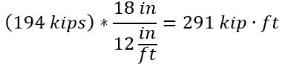
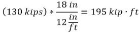
Note 4: AISC's bolt group load was converted to a moment capacity using the beam depth since that is the associated load AISC uses to compare to the capacity to. The calculated capacities are shown below.
LRFD
ASD
AISC flange plate bolt group strength:
AISC flange plate bolt group allowable:
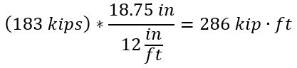
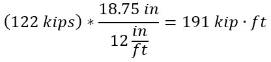
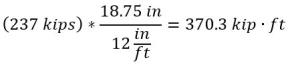
Note 5: AISC's flange plate load was converted to a moment capacity using the beam depth plus the flange plate thickness since that is the associated load AISC uses to compare the capacity to. The calculated capacities are shown below.
LRFD
ASD
AISC tension yield of flange plate strength:
AISC tension yield of flange plate allowable:
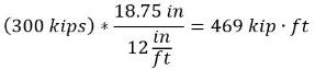
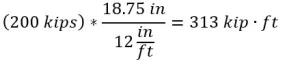
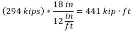
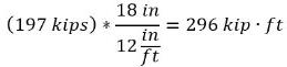
Note 6: AISC’s flange plate load was converted to a moment capacity using the beam depth plus the flange plate thickness since that is the associated load AISC uses to compare the capacity to. The calculated capacities are shown below.
LRFD
ASD
AISC block shear of flange plate strength:
AISC block shear of flange plate allowable:
Note 7: AISC’s flange load was converted to a moment capacity using the beam depth since that is the associated load AISC uses to compare the capacity to. The calculated capacities are shown below. AISC compares the allowable flange force to the flange force computed using the full beam depth of 18 in. SDS2 uses a moment arm of depth - tf ( 18 in - 0.75 in ) since this is the distance between the centroid of the beam flange forces. AISC uses lev = 1 1/4" to account for a 1/4" beam underrun. SDS2 uses the actual edge distance of
1 1/2". The AISC beam underrun assumption is considered a conservative engineering decision and is not a design requirement from the AISC design specification or manual. The beam underrun is also not considered in other applicable limit states.
LRFD
ASD
AISC block shear of flange plate strength:
AISC block shear of flange plate allowable:
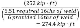
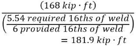
Note 8: AISC only determines a minimum fillet size of 3/8 in per the flange load. A capacity has been back calculated as the applied moment load divided by the unity.
LRFD
ASD
AISC rupture of flange weld strength:
AISC rupture of flange weld allowable:
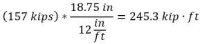
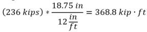
Note 9: Neither AISC nor SDS2 calculate this capacity directly in the calc. SDS2 calculates the tension/compression in a single calculation for the controlling load type. Both calculate an allowable flange plate compression force of 157 kips (SDS2/AISC ASD), 237 kip (AISC LRFD) or 236 kips (SDS2 LRFD). The moment capacities are back calculated as shown below.
LRFD
ASD
AISC compression of flange plate strength:
AISC/SDS2 compression of flange plate allowable:
SDS2 compression of flange plate strength: Note 10: AISC's column flange component capacities were converted to a moment capacity using the beam depth plus flange plate thickness as shown below.
LRFD
ASD
AISC column flange component strength:
AISC column flange component allowable:
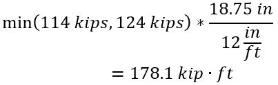
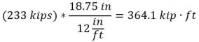
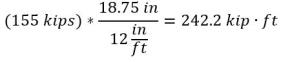
Note 11: AISC's column web component capacities were converted to a moment capacity using the beam depth plus flange plate thickness as shown below.
LRFD
ASD
AISC column web component strength:
AISC column web component allowable:
Note 12: Not checked by AISC, refers to AISC Design Guide 13.

References
-
AISC Committee on Manuals, Companion to the AISC Steel Construction Manual Volume 1: Design Examples, Version 16.0, American Institute of Steel Construction, 2023, https://www.aisc.org/publications/steel-construction-manual-resources/16th-ed-steel-construction-manual/manual-companion-for-16th-edition/.

