 Save Standard Detail ( Drawing Editor )
Tool summary :
Also see :
- Job standard detail (created with Save Standard Detail )
- Show ( Save Standard Detail acts on all layers marked " Show ")
- Set Selection Filters (affects Save Standard Detail )
- Create New (alternative for creating job standard detail)
- Verify Reference Point (to change reference point)
- Add Standard Detail (to add the newly created job standard detail)
page 1 | contents | edit > | edit -- area mode
 Quick instructions (also see the detailed instructions ) :
|
1 . Invoke Save Standard Detail . | |||
|
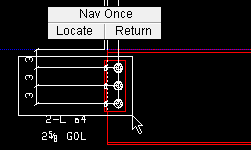
2 . Hold down the left mouse button ( Locate ) to draw an area box that establishes the clipping limits for 3D materials and other polygons. | |||
|
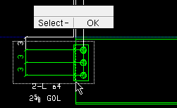
3 . Adjust the selection. In this example, the Ctrl key is held down and left-click ( Select - ) is used to deselect material lines inside the clipping limits. Right-click ( OK ) is used when adjusting the selection is done. | |||
|
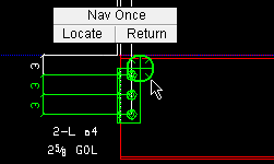
4 . The highlighted items preview the job standard detail. Left-click ( Locate ) a reference point to be used as the insertion point for the job standard detail. | |||
|
5 . On the Name Required window, give the standard detail a file name. | |||
|
6 . On the Area Save window, optionally enter a description, etc. |
|
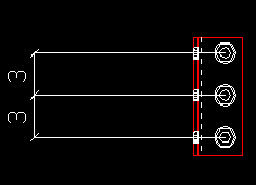
Save Standard Detail creates a job standard detail . It does not alter your current drawing. At left is the job standard detail created in the above example. |
page 1 | contents | edit > | edit -- area mode | top
 Detailed instructions (also see the quick instructions ) :
Be aware that polygons ( 3D materials , 3D bolts , 3D holes & clouds ) that are only partially within the clipping limits that you set in step 2 will be clipped. Tip: The highlighting in step 4 previews what the job standard detail will look like.
Before using this tool, you may want to:
1 . Invoke Save Standard Detail using any one (1) of the following methods:
Method 1 : Click the Save Standard Detail icon. The icon can be taken from the group named ' Edit -- Area Mode ' and placed on a toolbar (classic) or the ribbon (lightning).
Method 2 : If " Drawing Editor layout style " is ' Classic ', you can use the menu system to choose Edit > Save Standard Detail .
Method 3, 4 or 5 : Save Standard Detail can also be invoked using a keyboard shortcut , the context menu , or a mode . For the ' Lightning ' layout style, configuration of the interface is done using Customize Interface .
Method 6 : With Area Mode mouse bindings active, hold down the Shift key and left-click ( Save ).
2 . Locate- Pan -Return mouse bindings become active. The status line prompts, " Locate area clip bounds ." This step sets the clipping limits for 3D materials , 3D bolts , 3D holes & clouds . Tip: You can Set Selection Filters before setting the clipping limits.

2a : Define an area box by dragging your mouse pointer (
). Be aware that 3D materials, 3D bolts, 3D holes & clouds that are only partially within the clipping limits will be clipped. For left-to-right selection by area box, other objects (such as dimensions) must be entirely within the area box in order to be selected in this step. For right-to-left selection, any part of these other objects that are in the area box are selected.
3 . Select - Pan - Menu mouse bindings become active. A dotted rectangle shows the clipping limits you set in step 2. The status line prompts, " Adjust selection ."
|
|
|
bindings |
3a (optional) : Skip step 3b if the currently selected objects are the objects that you want to be saved into the job standard detail.
3b (optional) : Hold down the Shift key and Select + to select additional graphic object(s) that you want included in the job standard detail. Or you can draw an area box . To deselect objects, hold down the Ctrl key and left-click ( Select- ) the selected objects. You cannot select 3D materials , 3D bolts , 3D holes or clouds that are outside the clipping limits.You can Set Selection Filters when adjusting the selection.
3c : When the objects that you want included in the to-be-saved standard detail are selected, press the Enter key (or choose " OK " on the context menu ). Go to step 4.
4 . The program shows a preview of what the standard detail will look like -- only those objects or parts of objects that are currently highlighted will be included in the job standard detail. The status line prompts, "Locate a reference point." Various Locate options and Locate- Pan -Return mouse bindings become active.
|
|
|
bindings |
The reference point is used as the insertion point for the job standard detail when it is imported into other files using Add Standard Detail ; if you later find that you want to relocate this point, use Verify Reference Point .
Alternative 1 : Place your mouse pointer (
) so that the point location target snaps to the point on the drawing that you want to be the reference point, then left-click ( Locate ). Go to step 5.
Alternative 2 : Right-click ( Return ) to end the Save Standard Detail operation without creating a new job standard detail. Do not continue.
5 . The Name Required window opens.

Alternative 1 : To " Standard Detail name ," type the file name (up to 61 characters) that you want to give the job standard detail, then press the " OK " button. Go to step 6.
Alternative 2 : Press the " Cancel " button to end the Save Standard Detail operation without creating a new job standard detail. Do not continue.
6 . The Area Save window opens.
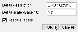
Detail description: The description (up to 22 characters) that will appear in the field " Material description " on the Drawing Data window for the job standard detail you are creating. It will also appear on the bill of material of that standard detail. Example: If you later place this standard detail into a member detail using Add Standard Detail , you can optionally place the description you entered here into that detail's bill of material.
Detail scale (Base 12 or 10) : The default scale entered here is the scale of your current drawing. If the words (Base 12) indicates the scale is in imperial units (X inch = one foot). (Base 10) indicates the scale is in metric units (X mm = 10 mm). If you change the scale, all graphic elements (except labels if the box for " Rescale labels " is checked) will automatically be resized.
Rescale labels: This option only applies if you have used the previous option to change the drawing scale. If this box is checked (
), labels on the job standard detail will be resized according to the new scale you have entered above. If the box is not checked (
), the labels will not be resized but will retain their current scale.

Alternative 1 : Press the " OK " button to close the window and save the job standard detail. Go on to step 7.
Alternative 2 : Press the " Cancel " button to end the Save Standard Detail operation without saving the job standard detail. Do not continue.
7 . The mouse bindings that were active before you invoked Save Standard Detail become again active. Your current drawing is totally unaffected by your having used this tool.
Tip: You can now, if you so choose, Open ( Ctrl + o ) the new job standard detail you just created. The new job standard detail has the file name you entered in step 5.
page 1 | contents | edit > | edit -- area mode | top

