Detail View Add ( Drawing Editor )
Tool summary :
| YouTube video: Detail Views and Member Style (Recorded in SDS2 Detailing , v2020i) |
|
Also see :
- Detail view drawings (topic)
- Detail view definitions and basic rules (topic)
- Drawing Editor (where Add Detail View is a tool)
- Detail View Area (window that opens when you Objects > Detail Views > Add )
- File > Open Detail View Drawing
- DETAIL VIEWS (a downloadable HOW/2 .pdf file)
- Magnifiers and Changing Member Style on the Fly (YouTube) (
 ) (Previously, detail views were called "magnifiers")
page 1 | contents | objects > detail views > | xxx add | detail view drawings
To add a detail view to a detail or submaterial or erection view in the Drawing Editor :
In Site Planning, a detail view can be added to a crane placement drawing .
1 . Invoke Detail View Add using any of the following methods:
Method 1 : Click the Detail View Add icon. The icon can be taken from the group named ' Objects -- Detail Views ' and placed on a toolbar (classic) or the ribbon (lightning).
Method 2 : If " Drawing Editor layout style " is ' Classic ', you can use the menu system to choose Objects > Detail Views > Add .
Method 3, 4 or 5 : Detail View Add can also be invoked using a keyboard shortcut , the context menu , or a mode . For the ' Lightning ' layout style, configuration of the interface is done using Customize Interface .
2 . Locate- Pan -Return mouse bindings are activated.
|
|
|
bindings |

In step 2a, you click and drag to define an area.

If you drag from upper left to lower right, the initial point will be the upper left corner of a rectangular area. 2a : Left-click ( Locate ) and drag your mouse pointer (
) diagonally to designate the area you want depicted in your detail view. This area is initially represented as a rectangle, but can made circular in step 3. For either a rectangle or a circle, the initial point where you begin to drag is a part of the rectangle or circle. For a rectangle, that point will be a corner of the rectangle.
3 . When you release the left mouse button in step 2a, the Detail View Area window opens.
3a (required) : Enter the " Annotation " that you want to call out the detail view. The " Annotation " is also used as part of the file name of the detail view drawing that this operation creates. The detail view drawing can be edited independently of the member detail or submaterial detail or erection view that you are currently performing this operation in.
3b (optional) : You can, if you so choose, change the " Area height " and " Area width " and " Area shape " (' Rectangular ' or ' Circular ') to define the area you drew in step 2a. Be aware that the choice you make for " Area shape " is final -- it cannot be edited after the detail view is generated.
3c (optional) : You can change the " Scale " and other attributes of the detail view if you so choose.
3d (optional) : Check the box for "
Show on original drawing ."
3e (required) : Press " OK " to close the Detail View Area window.
4 . Regardless of whether or not you checked the box for " ![]() Show on original drawing " in step 3d, Locate-Pan-Return mouse bindings are activated.
Show on original drawing " in step 3d, Locate-Pan-Return mouse bindings are activated.
|
|
|
mouse bindings |
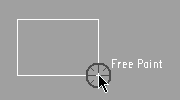
Alternative 1: Left-click ( Locate ) at the location on your unshortened drawing where you want to position the left, lower corner of the detail view. By default, Free Point is the point locator (snap) that is used to position the insertion point.
If you checked the box for "
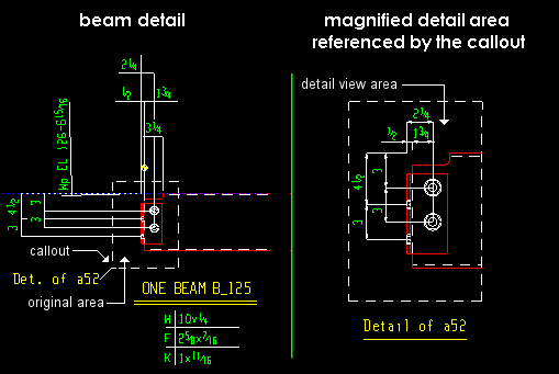
Show on original drawing ," an original area callout and detail view area are added to your current drawing. Also, a detail view drawing is created.
If you did not check the box for "
Show on original drawing ," the detail view area will not be added to your current drawing, but a detail view drawing will nevertheless still be created. Also, the callout area ( original area ) that you designated in step 2 will be drawn per the settings applied in step 3.
Note: File > Revert or Edit > Undo removes all changes to your current drawing and also automatically deletes the detail view drawing.
Alternative 2 : Right-click ( Return ) to end this operation without changing your current drawing.
page 1 | contents | objects > detail views > | xxx add | detail view drawings | top
