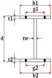
Welded plate wide flange (plate girder)
Shape file specifications:

|
d = depth
tw = web thickness t1 = top flange thickness g1 = top flange gage b1 = top flange width g2 = bottom flange gage b2 = bottom flange width t2 = bottom flange thickness |
Weld specifications in Shapes Properties : " Top flange weld type " and " Top flange weld size " are for welding the top flange to the web. " Bottom flange weld type " and " Bottom flange weld size " are for welding the bottom flange to the web. Shape file weld specifications set the weld symbols for shop welds shown in the 3D model and for shop weld symbols on member details.
Other shape file specifications: " Nominal Depth ," " Weight per Unit " (lbs/ft or kg/m), " Structural Properties ."
Additional settings that are not in the local shape file are defined on the Rolled Section Material window. In SDS2 Site Planning, these additional settings, as well as the shape file specifications, are read-only.
Section size naming convention: WPS+nominal_depth+x+nominal_weight/length (pounds/foot U.S.). For example, WPS12x50 . A welded plate wide flange section may be added to a shape file (in a full-featured SDS2 program ) using an entirely different naming convention.
Submaterial piecemarking: The default submaterial mark prefix for welded plate wide flange material is wpwf .
In Modeling and the Drawing Editor : A welded plate wide flange section must exist in the local shape file before the user of a full-featured SDS2 program can enter it as a " Section size " to a member or material edit window in Modeling , or before its weight will be automatically calculated when the user enters it to the " Description " field in the bill editor.
Available steel grades for welded plate wide flange material are defined in Home > Project Settings > Job > Plate Grades .
page 1 | contents | material types | shapes properties | top