The CNC Center Marks window
| Settings on this window are read-only . They tell you how this window has been set up for this Fabricator in a full-featured SDS2 program . |
- The Fabricator Options that you can review on this window set the placement of CNC marks on materials.
- These marks appear as X's on member main material in the model and on submaterial details and are used in the shop to identify the center of gravity of a member's main material and its top flange, near side, etc. They may optionally be shown on member details.
- When the user of a full-featured SDS2 program makes changes to this window, those changes directly affect automated functions that take place during Process and Create Solids .
page 1 | contents | home > project settings > fabricator > detailing > | classic | top
Method 1 : Home > Project Settings > Fabricator > Detailing > CNC Center Marks .
Methods 2, 3 & 4 : In Modeling or the Drawing Editor , choose Settings > Fabricator Settings > CNC Center Marks (classic), or use a keyboard shortcut , or click the icon.
page 1 | contents | home > project settings > fabricator > detailing > | classic | top
|
CNC marks are automatically dimensioned on submaterial details (as shown). They may also appear on member details . |
page 1 | contents | home > project settings > fabricator > detailing > | classic | top
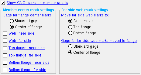
------ Settings ------
Show CNC marks on member details: ![]() or
or ![]() .
.
If this box is checked (
), then CNC marks will be represented as X's on system-generated member details.
If the box is not checked (
), CNC marks will still be generated, can still be CNC downloaded, will continue to be displayed in Modeling , and will continue to be dimensioned on submaterial details; they just won't be shown on member details.
------ Member center mark settings ------
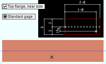
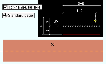
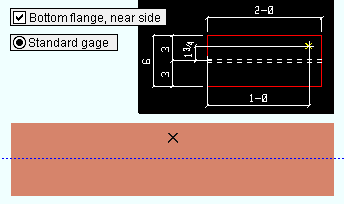
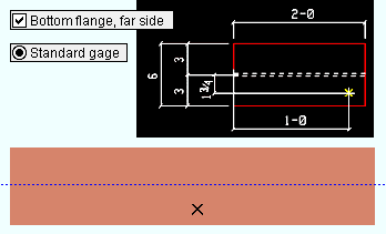
Gage for flange center marks: Center of flange or Standard gage .
|
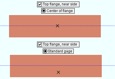
In both examples, " Top flange, near side " is checked. ' Center of flange ' is selected for the top example. ' Standard gage ' is selected for the bottom example. |
' Center of flange ' specifies that the mark be on the center line of the desired flange.
' Standard gage ' specifies that the mark be on the normal gage line of the member, per the standard gage as specified in the local shape file .
If this box is checked (
If the box is not checked (
If this box is checked (
If the box is not checked (
If this box is checked (
If the box is not checked (
If this box is checked (
If the box is not checked (
Bottom flange, near side: ![]() or
or ![]() .
.
If this box is checked (
If the box is not checked (
If this box is checked (
If the box is not checked (
page 1 | contents | home > project settings > fabricator > detailing > | classic | top
------ Far side web mark settings ------
Move far side web marks to: Don't move or Top flange or Bottom flange . This option is applicable when the box for " Web, far side " marking is checked.
' Don't move ' places far side web on the far side web. This means that CNC machines that do not have far side marking tools will be unable to replicate the marks without flipping the material.
' Top flange ' moves the far side web mark to the top flange. This might be done as an alternative to manually flipping the member over in order for the marks to be made on that side.
' Bottom flange ' moves the far side web mark to the bottom flange.
Gage for far side web marks moved to flange: Standard gage or Center of flange . This applies when " Web, far side " is checked AND " Move far side web marks to " is set to ' Top flange ' or ' Bottom flange '.
' Standard gage ' specifies that the mark be on the normal gage line of the flange, per the standard gage as specified in the local shape file .
' Center of flange ' specifies that the far side mark be moved to the center line of the desired flange.
page 1 | contents | home > project settings > fabricator > detailing > | classic | top