 The Clip Angle Settings setup window ( Fabricator Settings ) (read-only)
Settings that you can review on this read-only window work in coordination with individual clip angle type specifications and clip angle configurations to determine connection design in a full-featured SDS2 program when the " Input connection type ' is ' Clip angle ' or ' Auto standard ' or ' User defined '.
Also see :
- Clip angle input specs (settings for applying clip angles)
- Setup of clip angles (related setup options)
home > project settings > fabricator > standard fabricator connections > | classic
![]() To open Clip Angle Settings :
To open Clip Angle Settings :
Method 1 : Home > Project Settings > Fabricator > Standard Fabricator Connections > Clip Angle Settings .
Methods 2, 3 & 4 : In Modeling or the Drawing Editor , choose Settings > Fabricator Settings. > Standard Fabricator Connections > Clip Angle Settings (classic), or use a keyboard shortcut , or click the icon.
home > project settings > fabricator > standard fabricator connections > | classic | top
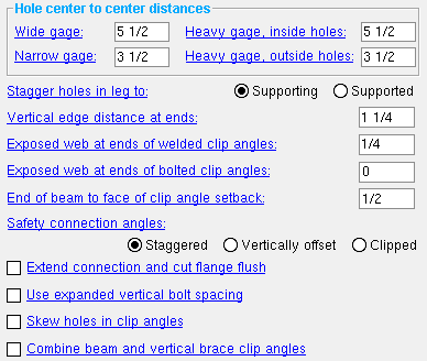
------ Hole center to center distances ------
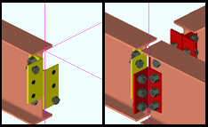
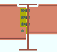
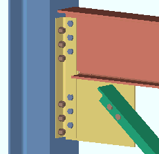
Wide gage: The center-to-center distance (in the primary dimension " Units " or in other units ) from the center of the column of holes on the one clip angle to the center of the column of holes on the other clip angle. This field applies to wide gage double clip angles.
|
g = gage. A full-featured SDS2 program designs wide gage clip angles when " Wide gage " has been specified on the Beam Edit window or for an auto standard or user defined connection. |
Effect on a full-featured SDS2 program: The double clip angle connection gage shown here applies in a full-featured SDS2 program to the connection design of wide gage double clip angles. Double clip angles are designed when " Both " is specified. Wide gage clip angles are designed when " Wide gage " clip angles are specified. This gage also affects the gages listed on the " Clip Angle Piecemarks " table for Wide Gage OSL All-Bolted Clip Angles and Wide Gage OSL Bolted/Welded Clip Angles clip angles.
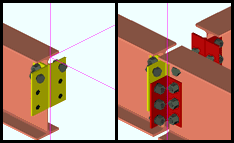
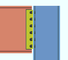
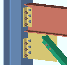
Narrow gage: The center-to-center distance (in the primary dimension " Units " or in other units ) from the center of one column of holes to another on narrow gage double clip angles.
|
|
g = gage. A full-featured SDS2 program designs narrow gage clip angles when " Narrow gage " has been specified on the Beam Edit window or for an auto standard or user defined connection. |
Effect on a full-featured SDS2 program: The double clip angle connection gage shown here applies in a full-featured SDS2 program to the design of narrow gage double clip angles. Double clip angles are designed when " Both " is specified. Narrow gage clip angles are designed when " Narrow Gage " is specified. The distance entered here also affects the gages listed on the " Clip Angle Piecemarks " table for Narrow Gage OSL All-Bolted Clip Angles and Narrow Gage OSL Bolted/Welded Clip Angles clip angles.
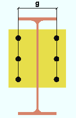
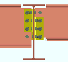
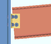
Heavy gage, inside holes: The center-to-center distance (in the appropriate " Units ") from the center of the inside column of holes on the one double clip angle to the center of the inside column of holes on the other clip angle.
Effect on a full-featured SDS2 program: The double clip angle connection gage shown here defines the distance between the inside bolt columns on heavy gage double clip angles. Heavy gage clip angles typically have two columns of bolts. Double clip angles are designed when " Both " is specified by the user for a heavy gage clip angle. Heavy gage clip angles are designed by when " Heavy " is specified by the user. The distance you enter here will also affect the gages listed on the " Clip Angle Piecemarks " table for Heavy Gage OSL All-Bolted Clip Angles and Heavy Gage OSL Bolted/Welded Clip Angles clip angles.
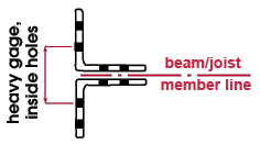
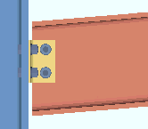
Heavy gage, outside holes: The center-to-center distance (in the appropriate " Units ") from the center of the outside column of holes on the one clip angle to the center of the outside column of holes on the other clip angle.
Effect on a full-featured SDS2 program: The center-to-center distance between outside holes shown here defines the dimension between the outside columns of holes on double heavy gage clip angles. Heavy gage clip angles typically have two columns of bolts.
home > project settings > fabricator > standard fabricator connections > | classic | top
------ Other clip angle setup settings ------
Stagger holes in leg to: Supporting or Supported . The selection shown here applies in default situations. The user of a full-featured SDS2 program can override the choice shown here using the " Stagger " option for individual connections.

If ' Supporting ' is selected, the full-featured SDS2 program staggers the holes in the leg of a clip angle that attaches to the supporting member.
If ' Supported ' is selected, the program will stagger the holes in the leg that attaches to the supported member.
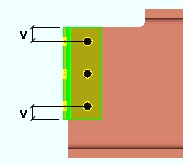
Vertical edge distance at ends: The distance parallel with the length of the clip angle (in the appropriate " Units ") from the outside edge of the clip angle to the center of the nearest hole. This applies to vertical brace gusset clips and horizontal brace gusset clips as well as to clip angles on beams.
|
v = vertical edge distance. |
Defaults: Per AISC specifications, the edge distance for clip angles is preset to a minimum of 1 1/4 inch (or 32 mm).
For clip angles on beams: The " Vertical edge distance at ends " applies to clip angles with bolts that have diameters that are less than or equal to 1 inch (24 mm). For clip angles with bolts that are larger than 1 inch (24 mm), connection design references Table J3.4 or Table J3.4M ( AISC Thirteenth Edition , p16.1-107).
For horizontal and vertical brace gusset clips: In general, connection design uses the maximum of the Table J3.4 value ( AISC Thirteenth Edition , p16.1-107) or the value entered to " Vertical edge distance at ends " when it designs clip angles for attaching the gusset of a horizontal brace or vertical brace to a supporting member. Two setup options that instruct connection design to override this general rule are: " Allow reduced edge distance for 7/8" and 1" bolts " (horizontal braces) and " Allow reduced edge distance for 7/8" and 1" bolts " (vertical braces).
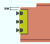
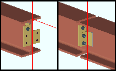
Exposed web at ends of welded clip angles: The vertical distance (in the primary dimension " Units " or in other units ) from the top (or bottom) of the clip angle to the cope on the supported beam. The exposed web distance entered here must be sufficient to allow the clip angle to be welded to the beam.
|
xw = exposed web. This distance must be sufficient to allow the clip angle to be welded to the beam. |
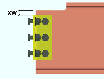
Exposed web at ends of bolted clip angles: The vertical distance (in the primary dimension " Units " or in other units ) from the top (or bottom) of the clip angle to the cope on the supported beam. Since no weld is required on a bolted clip angle, the exposed web can be set to 0 (zero) if desired.
|
xw = exposed web. Since no weld is required on a bolted clip angle, the exposed web can be set to 0 (zero) if desired. |
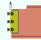
End of beam to face of clip angle setback: The horizontal distance (in the primary dimension " Units " or in other units ) between the end of the supported beam and the face of the clip angle (which fastens to the supporting member).
|
s = setback for the end of the beam to the face of the clip angle. |
Safety connection angles: Staggered or Vertically offset . This option is for clip angles on two beams framing to opposite sides of a supporting web (beam or column) so that the clip angle connections on both supported beams share bolts. The selection shown here applies when " Safety " has been selected for a clip angle connection. This will not work for bolted-bolted clip angles with staggered bolts.
|
|
|
' Staggered ' causes one angle of the double clip angles on a beam to moved down one bolt space so that one angle is staggered with respect to the other angle on the same beam. One bolt (either the upper or lower bolt) on each of the double clip angles will not be shared by the connecting clip angle on the opposing beam.
' Vertically offset ' moves both angles on one beam down one bolt space so that both angles are vertically offset with respect to the clip angles on the opposing beam. This will result in two "free" bolts at the top of the double clip angles on the one beam and two "free" bolts at the bottom of the clip angles on the opposing beam.
' Clipped ' produces staggered clip angles, with one clip angle shorter than the other so that each of the longer clip angles has one "free" bolt that is not shared by the clip angle on the opposing beam. To accomplish this, the NS angle on the left-end connection is cut one row shorter than the FS angle. On the right-end connection, the FS angle is one row shorter than the NS angle.
Extend connection and cut flange flush: ![]() or
or ![]() . The choice shown here applies when " Safety " has been selected for system-designed clip angle connections.
. The choice shown here applies when " Safety " has been selected for system-designed clip angle connections.
|
|
If this box is checked (
), connection design in a full-featured SDS2 program will be allowed to cut the flange flush to the web so that the safety clip angle can be bolted to the web.
If the box is not checked (
), the design routines will not be allowed to cut the flange flush in order to make the connection fit.
Use expanded vertical bolt spacing: ![]() or
or ![]() . This applies when ' Automatic ' is the choice made to " Use expanded vertical bolt spacing " for a particular ' Non-moment ' clip angle connection.
. This applies when ' Automatic ' is the choice made to " Use expanded vertical bolt spacing " for a particular ' Non-moment ' clip angle connection.
|
|

If this box is checked (
If the box is not checked (
A possible application: When an axial load (" Tension " or " Compression ") has been entered on the end of a beam with a clip angle, expanded vertical bolt spacing can promote uniform loading across the bolts.
Another application: Expanded vertical hole spacing can also help to reduce fabrication costs by minimizing the number of rows of bolts in clip angles.
Skew holes in clip angles: ![]() or
or ![]() . This applies to bolted clip angles on sloping beams when the box is checked for the " Square cut ends of sloped beams " setup option in Member Detailing Settings .
. This applies to bolted clip angles on sloping beams when the box is checked for the " Square cut ends of sloped beams " setup option in Member Detailing Settings .
|
|
If this box is checked (
If the box is not checked (
Combine beam and vertical brace clip angles: ![]() or
or ![]() . For a vertical brace to a beam and column, a full-featured SDS2 program designs clip angles for the gusset-to-column interface if the beam connects to the column with clip angles. This field sets the default for whether or not the clip angles are combined.
. For a vertical brace to a beam and column, a full-featured SDS2 program designs clip angles for the gusset-to-column interface if the beam connects to the column with clip angles. This field sets the default for whether or not the clip angles are combined.
|
|
If this box is checked (
If the box is not checked (
home > project settings > fabricator > standard fabricator connections > | classic | top