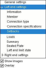
The Joist Review window

The navigation tree is contained in the left pane of the Joist Review window. It makes navigating the window easier.

Selecting a section name causes the settings in that section to be shown on the Joist Review window. In the example at left, " Setbacks " is selected and, as a result, the " Setbacks " leaf is expanded (as opposed to collapsed) ( VIDEO1 ). Sections are scrolled to when opened or, if they are already opened, when double-clicked ( VIDEO2 ).

To resize the pane containing the navigation tree, drag its right edge.

" Show images " (when checked) lets you see drawings that depict the dimensions that are controlled by connection design locks . ( VIDEO3 )

" Overlay " (when checked) displays one section at a time.

General settings
 Left end settings
 Right end settings

  General settings ------------------------------------------------------
  Section size   Panel display method ( )
  Piecemark   Marked for processing
  Piecemark group   Marked for detailing
  Surface Finish   Node-match job
  Sequence   Model complete
  Swap member ends   Model complete date
  Shape ( )   WP to WP length: plan
  Peak offset ( )   WP to WP length: actual
  Top chord radius   Lift assignment :
  Joist rotation   Bay pitch : ( )
ABM options apply to a joist's " Section size " -- the joist's main material.

General settings
User preconfigured panel
 Left end settings
 Right end settings

  User preconfigured panel -----------------------------------------------------
Panel layout   Panel member material
    Configuration
    Panel section size

Left end settings
Right end settings

General settings
User preconfigured panel
   Left/Right end settings
        Information


Connection Changed Message Connection Failure Message
  Connection :   Connection :
 
context-sensitive help

General settings
User preconfigured panel
   Left/Right end settings
        Information
        Member


  Member   --------------------------------------------------------------- --
  Top of joist ( )   Bearing shoe ( )
  Supporting chord   Input elevation
 

General settings
User preconfigured panel
   Left/Right end settings
        Information
        Member
        Profile


  Profile   --------------------------------------------------------------- --
  Shoe length   Bottom chord pitch
  Shoe pitch   Triple pitch peak offset
  Top chord pitch  
 

General settings
User preconfigured panel
 Left/Right end settings
        Information
        Member
        Profile
        Connection type


  Connection type -------------------------------------------------- --
  Input connection type ( )   NM bolt diameter
  User defined connection   Use miscellaneous plates list
  System designed connection   Disable framing situation checks
  NM bolt type  
 

General settings
User preconfigured panel
   Left/Right end settings
        Information
        Member
        Profile
        Connection type
        Connection specification


  Connection specifications ---------------------------------- --
  Chord to support   Extend bottom chord
  Top chord seated material   Stabilizing material
  Seat to supporting member   Use erection hole
 top chord Schedule entry   Vertical stabilizer angle
 top chorid embed Location  bottom chord Schedule entry
  Allow washers on bearing shoe slots  bottom chord embed Location

General settings
User preconfigured panel
   Left/Right end settings
        Information
        Member
        Profile
        Connection type
        Connection specifications
        Setbacks & extensions

  Setbacks and Extensions ------------------------------------- --
  Top chord ( )   Bottom chord ( )
  Shoe  
 

General settings
User preconfigured panel
   Left/Right end settings
        Information
        Member
        Profile
        Connection type
        Connection specifications
        Setbacks & extensions
        Loads

  Loads -------------------------------------------------------------- --
  Load  
 

General settings
User preconfigured panel
   Left/Right end settings
        Information
        Member
      Profile
        Connection type
        Connection specifications
        Setbacks & extensions
        Loads
        Connection Design Locks

      Seated Tee ( for a joist top chord )
      Seated Plate ( for a joist top chord )
      Seated Angle ( for a joist top chord )
      Joist Stabilizer Angle ( for an extended bottom chord )
      Joist Stabilizer Plate ( for an extended bottom chord )
      Bearing Shoe Slots
      Bolts
      Joist End Pocket ( joist to a concrete wall or panel )

General settings
User preconfigured panel
 Left/Right end settings
        Information
        Member
      Profile
        Connection type
        Connection specifications
        Setbacks & extensions
        Loads
        Limit state

  Right/Left end limit state --------------------------------------------------------------------------

--- The capacity of a connection is calculated for various limit states during connection design .

--- Connection design takes place in a full-featured SDS2 program , but not in SDS2 Site Planning.

--- You can review the results of connection design by reviewing connection design locks , by outputting a Connection Design Calculations Report or the Expanded Connection Design Calculations , or by visual inspection of the model.

To open the Joist Review window :

Also see :

contents | model > member | top