The 3D Model - Q & A (topic)
On this page :
- What is the 3D model?
- Why is it called three-dimensional?
- Where does the 3D model come from?
- How can I look at the model?
- What is the importance of the 3D model?
- How does 3D modeling benefit construction?
- Doesn't 3D modeling take longer?
Also see :
A . The 3D model is a computer representation of the actual steel framework of a building, tower or other steel structure. It is also a database of information about members that make up the steel structure. The 3D model that you can review using a SDS2 review station is contained in your current Job .
page 1 | contents | topics | top
Q. Why is it called three-dimensional?
A . Because it is three-dimensional. It exists in a 3D mathematical matrix, sometimes referred to in this documentation as the global coordinate system . Every member in the 3D model has actual physical dimensions that can be measured on screen; each end of each member exists at a particular elevation. Each member or material work point is assigned unique X, Y and Z coordinates within a 3D mathematical matrix.
page 1 | contents | topics | top
Q. Where does the 3D model come from?
A . It is created by a user in the Modeling portion of a full-featured SDS2 program . Users of a SDS2 review station can review the model, but cannot make any changes to it.
page 1 | contents | topics | top
Q. How can I look at the model?
A . The obvious answer to this question is that you can look at it on your computer screen. However, things are actually more complicated than that. The model, after all, exists in three dimensions, while your computer screen is flat and therefore can only represent 3D space in two dimensions. SDS2 programs let you view the model through something called an erection view, which is a 2D window into the 3D model.
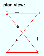
A plan view looks down into the model from a particular Reference Elevation . The reference elevation is the plan view's work plane . A plan view can be created using View > Plan View . Items that are above or below the Reference Elevation will be shown to the depth checking limits of the view (if " Depth checking " is on), or without limits if " Depth checking " is off.

|
axes :
|
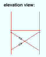
An elevation view looks at the model from its side. An elevation view also has a work plane , which can be changed using View > Relative Depth . A permanent elevation view can be created in a full-featured SDS2 program and opened using Open View . View > Section View is another way to access an elevation view.
|
axes :
|

|
axes :
|
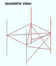
An isometric view looks at the model from an angle. An isometric view does not have a specific work plane.

|
axes :
|
By going into different erection views, you will be able to look at the model from different perspectives, each of which will provide you with information about the various members that make up the 3D model.
page 1 | contents | topics | top
Q. What is the importance of the 3D model?
A . The basic theory behind the SDS2 family of programs is that if you construct the 3D model properly, then all of the information that you derive from the 3D model will be accurate and up to date. All shop drawings and erection drawings that are automatically generated in a full-featured SDS2 program derive their information from the 3D model. Therefore, if there is a structural problem with a SDS2-generated detail drawing, the way to fix it is to correct the problem in the 3D model, then regenerate the detail drawing. Many reports that can be generated in SDS2 programs also derive their information from the 3D model. Some reports are derived from member bills of material, but member bills of material are themselves derived from the 3D model. Because all information that comes from an SDS2 program is ultimately derived from a single 3D model, conflicting information is minimized and the people who depend on SDS2 -- engineers, detailers, shop personnel, warehouse personnel, etc. -- will all be getting information that is crucial to their job performance from the same source.
page 1 | contents | topics | top
Q. How does 3D modeling benefit construction?
A . With 3D modeling, you can actually see a structural framework before the structure is erected. This greatly aids in your ability to troubleshoot potential problems before they become real problems. If you think that there is a problem with the way that a particular member end connection is designed, you can go to the model and look at that end connection to see how it will actually appear in real life. If a beam is too short, you will be able to see on your computer screen that it is too short. 3D modeling helps to ensure that all members will be designed and fabricated to precise specifications so that members fit together exactly the way they are supposed to and actual erection of a structure at its construction site is greatly facilitated.
page 1 | contents | topics | top
Q. Doesn't 3D modeling take longer?
A . Not really. When a user of a full-featured SDS2 program does 3D modeling work in Modeling , that user is also doing the ground work for creating detail drawings -- which can be generated automatically (and therefore very quickly). While learning an SDS2 program initially requires an investment of your time, the program will quickly a real time saver. In addition to saving drawing time, SDS2 programs save time in troubleshooting and revisions. It saves time by ensuring that all who depend on information from the model are provided with the same information (because that information ultimately comes from the same source -- the model). It saves time by helping users to visualize potential problems before they become real problems at the actual construction site. SDS2 programs also save the time and hassle and money associated with the back charges that 3D modeling can help to prevent.


