The Hole Edit window ( Drawing Editor )
Settings on this window are read-only if you are editing a hole that is not on a comment layer . If the hole is on a comment layer, you can revise its settings. You can also add holes to comment layers.
" Machine / Tool operations " are editable on this window when the selected " Hole type " is ' Machine / Too l'.
- To open this window:
- Hole Add
- Hole Edit or double-click a hole
Also see :
- Holes (topic)
- Filled hole pen color ( Drawing Presentation , Fabricator Setup )
contents | objects > holes > | objects -- holes | top
![]() " Copy " " Paste " " Save " " Load " buttons
" Copy " " Paste " " Save " " Load " buttons
These buttons appear on this window only if the hole (or holes) you are editing are on a comment layer .
You'll find buttons like these at the top of this window. They apply to all user-editable settings that are on this window. Click here for more information.
You can " Copy " (
) the settings on this window, then change the " Hole__of " number you are editing using the VCR buttons, then " Paste " (
) those settings to the newly selected hole.
" Save " (
) saves a file to the form/hole folder (
) that is used by your current version of this program. Give the file a name that will help users in other Jobs on your network identify its purpose. " Load " (
) changes all settings on this window to those settings that are stored in the file that you select.
" Paste " and " Load " replace mixed entries to a single field with a single entry. " Copy " and " Save " ignore fields with mixed entries, treating them as if they have no entry or do not exist.
contents | objects > holes > | objects -- holes | top
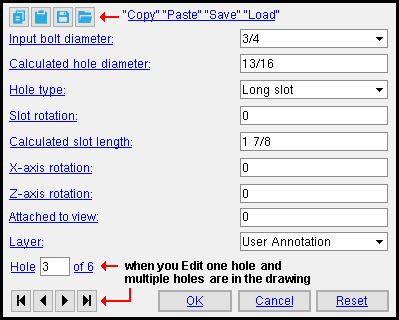
Input bolt diameter: The diameter (inches or mm) of the shaft of the bolt to be inserted into the hole. This value is used to set the " Calculated hole diameter ."
| diameter |
|
Setup: You can type in a diameter, or select a bolt diameter from the combo box's menu (
). Diameters listed on the menu come from the Available Bolts list in Bolt Settings.
Calculated hole diameter: A system-calculated or user-entered distance. On a ' Standard round ' hole, the calculated value will typically be 1/16 inch larger than the input bolt diameter.

dia = diameter
To add a CNC mark, enter a diameter of ' 0 ' (zero). An "X" is used to represent a CNC mark in a view (or, for that matter, on a detail drawing).
Hole type: Standard round or Short slot or Long slot or Oversized or Machine / Tool .
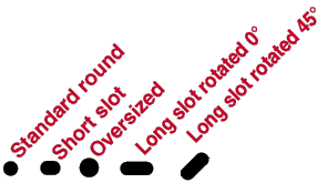
A ' Standard round ' hole is perfectly round and will typically input a " Calculated hole diameter " 1/16 inch larger than the input bolt diameter.
An ' Oversized ' hole will typically input a " Calculated hole diameter " 1/8 inch larger than the input bolt diameter.
A ' Short slot ' hole is oblong in shape and has a relatively short " Calculated slot length ."
A ' Long slot ' hole is oblong in shape and has a longer " Calculated slot length ."
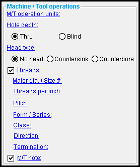
' Machine / Tool ' enables the " Machine / Tool operations " on this window so that you can specify a threaded thru hole or a blind hole or a counterbore hole or a countersink hole.
Slot rotation: A positive or negative (-) value from 360 to -360 degrees. This field will be grayed out for ' Standard round ' or ' Oversized ' hole types. Slot rotations can be modeled to a precision of 0.1 degree.
| <= X screen axis => |
|
|
' 0 ' (zero) degrees signifies horizontal with respect to the screen and is the default setting if the " Hole type " is ' Long slot ' or ' Short slot '.
A ' positive number ' of degrees rotates the slot counterclockwise from horizontal.
A ' negative (-) number ' of degrees rotates the slot clockwise from horizontal.
Calculated slot length: A specific calculated distance (in the primary dimension " Units " or in other units ) between the two points farthest from one another on the perimeter of a slot. This field is disabled when the " Hole type " is ' Standard round ' or ' Oversized '. It is only valid for ' Long slot ' or ' Short slot '.

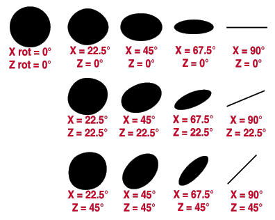
X axis rotation: A positive or negative (-) value from 180 to -180 degrees that sets the amount of rotation of the hole around the X screen axes . For this option to be active, the hole must have been added by locating the same point twice.
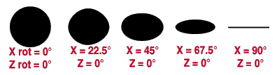
Tip: This option can be used with " Z axis rotation " (see below) to represent holes in skewed material.
Z axis rotation: A positive or negative (-) value from 180 to -180 degrees that sets the amount of rotation of the hole around the Z screen axes . For this option to be active, the hole must have been added by locating the same point twice.
holes in this example have the same diameter
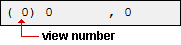
Attached to view: A number designating the view that this hole is attached to. For instance, a column detail may have a view of face A, face B and face C. It may also have various section views (Section A-A, Section B-B, Section C-C). All graphical objects that are in a particular view are assigned the same number.
Assigning the correct number to an object (line, weld symbol, label, etc.) provides maximum compatibility when the comment layer you add that object to is viewed or printed in a full-featured SDS2 program . System-generated submaterial details and member details are the two Drawing Editor drawing types that can have multiple views.
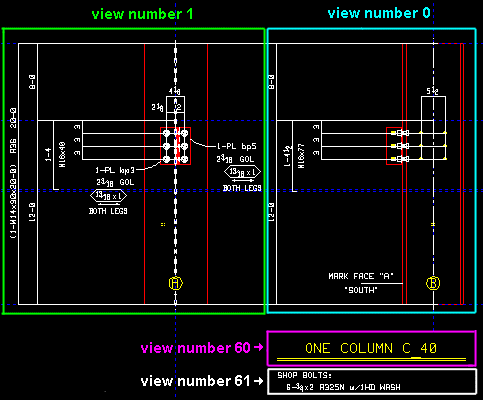
To show a view's number, you can add the X-Y-Z Display to your toolbar.
In the Drawing Editor , the X-Y-Z Display shows the view number that the point location target (
) is over.
Layer: Any drawing layer (any layer given a " Name ") in your current drawing. This is the drawing layer that the hole you are adding or editing will be drawn on after you press " OK " to close this window. If that layer happens to be a hidden (not " Shown ") layer, the hole will disappear after the first Redraw .
![]()
If the layer listed here is a non-comment layer: Options on this window are read-only .
If this window is editable: You can only select a comment layer from the list box's selection menu (
Defaults: For an Add Hole operation, the default selection (
contents | objects > holes > | objects -- holes | top
------ Machine / Tool operations ------
| Please note: For these options to be enabled, the " Hole type " must be ' Machine / Tool '. Choices you make to " Machine / Tool operations " affect the callout that you get when you Objects > Material Callout > Add a callout to the machine hole. |
M/T operation units: ![]() Imperial or
Imperial or ![]() Metric .
Metric .
'
Imperial ' lets you make distance entries to fields in this section in the primary dimension " Units " that are specified in Drawing Presentation in Fabricator Setup . Be aware, though, that you can still make entries in other units .
'
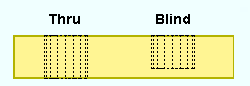
Hole depth: ![]() Thru or
Thru or ![]() Blind . The " Hole type " for a blind hole must be ' Machine / Tool '.
Blind . The " Hole type " for a blind hole must be ' Machine / Tool '.
'
'
VIDEO 
Hole information for a blind hole is shown on a miscellaneous member detail. (Recorded in SDS2 Detailing , v2016) 'Depth' is the length of the blind hole in the " M/T units ."
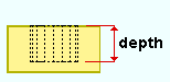
A blind hole's depth is the distance from the material's surface to the bottom of the hole.
A label on a member deta il indicating that the depth of a blind hole is 0.75 inch.
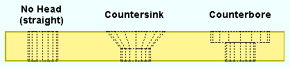
Head type: ![]() No head (straight) or
No head (straight) or ![]() Countersink or
Countersink or ![]() Counterbore . The " Hole type " for a countersink or counterbore hole must be ' Machine / Tool '.
Counterbore . The " Hole type " for a countersink or counterbore hole must be ' Machine / Tool '.
'
'
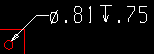
VIDEO A label for a countersink hole with threads is shown on a member detail. (Recorded in SDS2 Detailing , v2016)
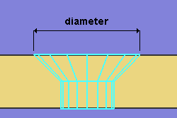
A callout on a member detail that specifies a 0.81 inch hole with a countersink diameter of 1.63 inch and an angle of 82 degrees. 'Diameter' is the countersink hole's maximum diameter (in the " M/T units ").. The hole is at its maximum diameter at the surface of the material.
|
The diameter of the hole at the end opposite to the countersink is the " Hole diameter " or, if the hole is threaded, the " Major dia ." |
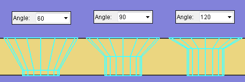
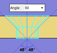
'Angle' is the angle of the countersink (in degrees). This is the angle between opposite sides of the countersink conical bore. You can enter any number of degrees that you like, or you can select a value from the combo box menu.
|
The specified " Angle " (' 90 ' in this example) sets the angle between opposite sides of the countersink cone. |
'
VIDEO Hole information for a counterbore hole is shown on a miscellaneous member detail. (Recorded in SDS2 Detailing , v2016)
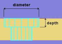
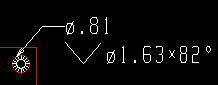
A counterbore is defined by its " Diameter " and a " Depth ."
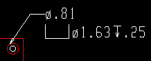
A label on a member detail that calls out a 0.81 inch hole with a counterbore diameter of 1.63 inch and a counterbore depth of 0.25 inch. 'Diameter' is the counterbore diameter (in the " M/T units ") at the surface of the material.
'Depth' is the length of the counterbore (in the " M/T units "). This distance is from the material's surface to the bottom of the counterbore.
Threads: ![]() or
or ![]() . The " Hole type " for a hole with threads must be ' Machine / Tool '. The hole can be a blind hole or thru hole or have any " Head type ."
. The " Hole type " for a hole with threads must be ' Machine / Tool '. The hole can be a blind hole or thru hole or have any " Head type ."
|
If this box is checked (
), options such as " Threads per inch " or " Pitch " and " Direction " are enabled, and you can use them to define hole threads. Thread settings will affect the callout that you get when you Objects > Material Callout > Add a callout to the threaded hole.
If the box is not checked (
), then hole thread settings are disabled, and the hole will not be threaded.
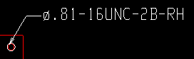
Major dia. / Size #: The nominal diameter of the threaded hole. This is the threaded portion of a hole's largest diameter or outside diameter. The " Major dia. " value entered here is printed in the callout that you get when you Objects > Material Callout > Add a callout to the threaded hole.
When " M/T units " is ' Imperial ', a diameter symbol ø precedes the major diameter value, which is expressed in decimal inches.
|
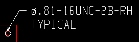
ø.8 1 = " Major dia. " (inch) 16 = " Threads per inch " UNC = " Form / Series " 2 = " Class " RH = " Direction " |
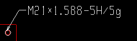
When " M/T units " is ' Metric ', the letter M precedes the major diameter, which is expressed in millimeters. In the example below, the major diameter is 21 mm.
|
M21 = " Major dia. " (mm)
1.588 = " Pitch " 5H/5g = " Class " |
Threads per inch: This is the count of the threads per inch (TPI) along the depth of the hole. This applies when " M/T units " is ' Imperial '. If you change the " M/T units " to ' Metric ', the name of this field will be changed to " Pitch " and the TPI value you entered will be converted to pitch. The TPI value entered here is recorded to the callout that you get when you Objects > Material Callout > Add a callout to the threaded hole. TPI does not affect the representation of a hole in Modeling .
|
|
ø.81 = " Major dia. " (inch) 16 = " Threads per inch " UNC = " Form / Series " 2 = " Class " RH = " Direction " |
| Threads per inch (TPI) is the inverse of " Pitch ." For example, if the threads per inch are 32, then 1/32 (the inverse) = 0.03125 inch. Converting this to mm gives you: 0. 0.031250 inch x 25.4 mm/inch = 0.79375 mm. Thus, in a standard table of screw threads, a TPI of 32 is equal to a pitch of 0.7938 mm. |
Pitch: The distance between thread peaks in millimeters. Pitch is the inverse of threads per inch, but expressed in mm: In other words, pitch is millimeters per thread. " Pitch " is available as an entry field when the " M/T units " is ' Metric '. The pitch value that you enter here is recorded to the callout that you get when you Objects > Material Callout > Add a callout to the threaded hole.. Pitch does not affect the representation of a hole in Modeling .
|
|
M21 = " Major dia. " (mm)
1.588 = " Pitch " 5H/5g = " Class " |
Form / Series: None or UNC (coarse) or UNF (fine) or UNEF (extra fine).. This applies when " M/T units " is ' Imperial ' and " ![]() Threads " is checked. The value that you enter here is recorded to the callout that you get when you Objects > Material Callout > Add a callout to the threaded hole. In the example below, the series is UNC (coarse).
Threads " is checked. The value that you enter here is recorded to the callout that you get when you Objects > Material Callout > Add a callout to the threaded hole. In the example below, the series is UNC (coarse).
|
|
ø.81 = " Major dia. " (inch) 16 = " Threads per inch " UNC = " Form / Series " 2 = " Class " RH = " Direction " |
' None ' results in the form / series not being included in the hole callout label. If ' None ' had been selected for the above example, the label would read: ø.81-16-2B-RH ,
' UNC ' stands for Unified National Course. For the example above. 'UNC' was selected as the "Form / Series," and therefore the label reads ø.81-16UNC-2B-RH ,
' UNF ' stands for Unified National Fine. If 'UNF' had been selected for the example above, the label would read ø.81-16UNF-2B-RH .
' UNEF ' stand for Unified National Extra Fine. For the example above. 'UNEF' was selected as the " Form / Series ," and therefore the label reads ø.81-16UNC-2B-RH ,
Class: 1 or 2 or 3 or 6H/6g or etc. . " Class " is a designation of tolerance, or the closeness of fit between two mating parts. You can type in any class you like, or you can select a class from the combo box menu. The class you specify is recorded to the thread information line on the callout that you get when you Objects > Material Callout > Add a callout to the threaded hole. Class does not affect the representation of a hole in Modeling . In the example below, the class is 2, and B indicates that the thread is internal.
|
|
ø.81 = " Major dia. " (inch) 16 = " Threads per inch " UNC = " Form / Series " 2 = " Class " RH = " Direction " |
When " M/T units " is ' Imperial ': 1
'' indicates generous tolerance.' 2 ' designates normal production. If no class is designated, common practice is to assume that 2 is the class. .
' 3 ' designates high accuracy.
Note: The letter B in the imperial example shown above indicates internal thread, i.e., threads in a hole, the female part. A nut would also have internal threads. The letter A would indicate external threads, i.e., threads in a screw, the male part.
M21 = " Major dia. " (mm)
1.588 = " Pitch "
5H/5g = " Class "When " M/T units " is ' Metric ':
' 6H/6g ' indicates general purpose. If no class is designated, common practice is to assume that 6H/6g is the class.' 4H/4g ' and ' 5H/5g ' and ' 7H/7g ' are a few other selections that you can make to
As stated above , you can type almost any value you like to this combo box .
Direction: ![]() RH or
RH or ![]() LH . In the example below, the direction is RH (right-handed).
LH . In the example below, the direction is RH (right-handed).
|
|
ø.81 = " Major dia. " (inch) 16 = " Threads per inch " UNC = " Form / Series " 2 = " Class " RH = " Direction " |
'
'
Termination: ![]() Thru or
Thru or ![]() Thread depth .
Thread depth .
'
'
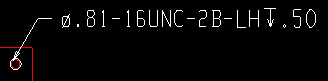
The " Depth " specified for this example is 0.5 inch. 'Depth' is the length of the threads (in the " M/T units "). This distance is from the material's surface to the depth of the hole at which you want the threads to end.
M/T note: Any text can be entered, including Latin 1 characters 0160 to 0255 . To enter special characters, hold down the Alt key and type in the number, or copy and paste from the Character Map that can be launched from your operating system's Accessories menu. To enter multiple lines, press the Enter key where you want a line break. The line(s) of text that you enter will appear below other lines in the callout that you get when you Objects > Material Callout > Add a callout to the threaded hole.
|
TYPICAL is the " M/T note " in this example of a hole callout label. |
contents | objects > holes > | objects -- holes | top
For Edit Hole operations on comment layers only :
Hole _ of __ (not applicable to Add Hole or multiple edit) : The number of the one hole you are editing and the total count of all holes in your current drawing. You can use the VCR buttons to select a different hole that is on a comment layer and edit that hole while still on this window. When a hole on a shown layer is selected, it is displayed in green. The selected hole must be on a shown layer for it to be shown.
|
|
| VCR buttons (first-previous-next-last) for selecting a hole to edit. |
Note: If you change one hole, then select a different hole number, the first hole remains changed even if you press " Cancel " on this window.
contents | objects > holes > | objects -- holes | top
Possibility #1 :
Press the " OK " button if this window is for review only
(if you are editing a hole that is not on a comment layer ).
Possibility #2 :
If you are adding or editing a hole on a comment layer,
the bottom of this window will show the following buttons:
![]()
![]()
![]()
"OK" (or the Enter key) closes this window and completes the Hole Add or Hole Edit operation.
Defaults: When you press " OK ," the settings on this window -- except mixed entries -- become the default settings for the next hole you Add during this session of the Drawing Editor . Even if all you do is double-click a hole that is on a comment layer and press " OK " without making any changes on this window, this window's settings become the defaults for the next-added hole. The settings on this window do not become the defaults for new holes if you press " Cancel " to close this window (unless you used the " Hole _ of __ " widget).
"Cancel" (or the Esc key or the ![]() button) closes this window without saving any of the changes you have made. " Cancel " only cancels the changes made to the hole whose number is currently selected in the " Hole _ of __ " widget.
button) closes this window without saving any of the changes you have made. " Cancel " only cancels the changes made to the hole whose number is currently selected in the " Hole _ of __ " widget.
Tip 1: Although " Cancel " does not cancel changes made to more than one hole, Undo (after you have closed this window) undoes all changes made using this window.
Tip 2: If you double-click a hole that is on a comment layer just to review it and don't want to set the defaults for to-be-added holes, the best way to close this window is to press " Cancel. "
"Reset" undoes all changes made to the hole whose number is currently selected in the " Hole _ of __ " widget. The window remains open.