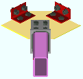
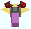
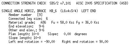
The Horizontal Brace Review window ( Modeling ) (" Status " & " Properties " enabled )
page 1 | contents | review | top
|
|||||
|
|
||||
Section size: The main material (e.g., ' L9x4x5/8 ') of the brace(s). Only materials listed in the local shape file can be specified here.
|
|||||||||||||
Piecemark or System piecemark or User piecemark or Frozen piecemark :
Sequence :
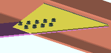
Long leg: Outstanding or To gusset . This " ![]() General settings " option applies when an angle with unequal legs has been entered as the horizontal brace's " Section size ."
General settings " option applies when an angle with unequal legs has been entered as the horizontal brace's " Section size ."

|
' Outstanding ' bolts the short leg of the angle to the gusset. For a non-sloping horizontal brace, this makes the long leg vertical. |
|
' To gusset ' bolts the long leg of the angle to the gusset plate. For a non-sloping horizontal brace, this makes the long leg horizontal. |
Double material: ![]() or
or ![]() . This "
. This " ![]() General settings " option applies when an angle has been entered as the horizontal brace's " Section size ."
General settings " option applies when an angle has been entered as the horizontal brace's " Section size ."
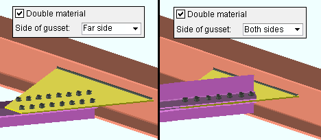
If this box is checked (
), the horizontal brace is a double angle brace. The angles are back-to-back if either ' Near ' or ' Far ' is selected for " Side of gusset ." One angle is on the far side of the gusset and the other is on the near side if both ' Both sides ' are selected for " Side of gusset ."
If the box is not checked (
), the horizontal brace is a single angle.
One gage line: ![]() or
or ![]() . This "
. This " ![]() General settings " options applies when an angle has been entered as the horizontal brace's " Section size ."
General settings " options applies when an angle has been entered as the horizontal brace's " Section size ."
|
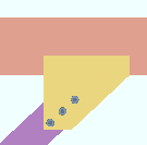
If this box is checked ( |
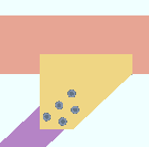
|
If the box is not checked ( |
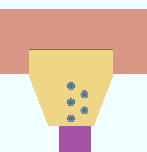
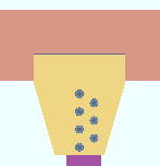
Stagger bolts: ![]() or
or ![]() . This "
. This " ![]() General settings " option applies when an angle has been entered as the horizontal brace's " Section size " and the leg to gusset is 5 inches (127 mm) or longer.
General settings " option applies when an angle has been entered as the horizontal brace's " Section size " and the leg to gusset is 5 inches (127 mm) or longer.
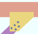
|
If this box is checked ( |
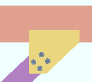
|
If the box is not checked ( |
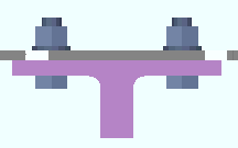
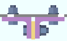
Side of gusset: Near side or Far side or Both sides . This " ![]() General settings " option is for selecting the face of the gusset plate for attachment of an angle or tee or double angle horizontal brace.
General settings " option is for selecting the face of the gusset plate for attachment of an angle or tee or double angle horizontal brace.

|
' Near side ' fastens the horizontal brace to the near side face (the top face) of the gusset plate. The near side face is the face that you look down on in a plan view. |

|
' Far side ' fastens the horizontal brace to the far side of the gusset plate (the bottom face of the gusset plate). |

|
' Both sides ' only applies when the box for " Double material " is checked. The program uses the " Type of spacer " that is specified in Member Detailing and Fabricator Options . |
Long side: Vertical or Horizontal . This " ![]() General settings " option applies when a tube has been entered as the horizontal brace's " Section size ."
General settings " option applies when a tube has been entered as the horizontal brace's " Section size ."
|
' Vertical ' indicates that the long side of the tube brace is vertical.
' Horizontal ' indicates that the long side of the tube brace is horizontal.
Status Display: Member status > HSS long side orientation
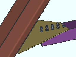
Allow material workline offset: Automatic or Yes or No The top surface of, for example, an angle or W tee horizontal brace is normally in the same plane as the brace's work line . This " ![]() General settings " option gives connection design (in a full-featured SDS2 program) permission to offset the main material of a brace so long as that brace has at least one end that frames to a beam's bottom flange. The option does not affect most horizontal braces.
General settings " option gives connection design (in a full-featured SDS2 program) permission to offset the main material of a brace so long as that brace has at least one end that frames to a beam's bottom flange. The option does not affect most horizontal braces.
|
A material workline offset is allowed when a horizontal brace frames to the bottom flange of a beam. To get a connection in such a situation, the beam workline must be in the same plane as the beam's bottom flange. |
' Automatic ' applies the choice made to " Allow material workline offset " in Member Detailing & Fabrication Options ( Fabricator Setup ).
' Yes ' allows connection design (in a full-featured SDS2 program ) to offset the main material of the horizontal brace by the thickness of the gusset plate so that the brace can connect to the bottom flange of the beam. This affects both connections on the brace, even if, for example, one end of the brace goes to the bottom flange of a beam and the other end goes to the web of a different beam..
' No ' indicates that the main material of the brace is not offset. If at least one end of the brace frames to the bottom flange of a beam, the connection on that end will fail with the message " Invalid brace work point location ."
Minimum gusset thickness: Auto or a user-entered thickness (in the primary dimension " Units " or in other units ).
If " Auto " is checked (
), then a full-featured SDS2 program designs a gusset plate that is as thick or thicker than the Home > Project Settings > Fabricator > Standard Fabricator Connections > Gusset Plate Settings > " Minimum gusset plate thickness ."
If " Auto " is not checked (
), a gusset plate is designed to be as thick or thicker than the minimum thickness shown here.
Locate on neutral axis: Automatic or Yes or No . This " ![]() General settings " option applies when the horizontal brace's " Section size " is an angle . No matter what choice is made here, the work line of the horizontal brace runs along the surface of the angle leg that attaches to the gusset.
General settings " option applies when the horizontal brace's " Section size " is an angle . No matter what choice is made here, the work line of the horizontal brace runs along the surface of the angle leg that attaches to the gusset.
|
workline ( x )
on neutral axis |
workline ( x )
on gage line |

|
|
' Automatic ' indicates the horizontal brace angle material is aligned with its work line per the choice made to Home > Project Settings > Fabricator > Member Detailing & Fabrication Options > the " Horizontal Braces " section > " Locate angle braces on neutral axis ."
' Yes ' indicates that the angle material's X-X axis or Y-Y axis (shown in the AISC Structural Shapes tables) intersects with the workline of the brace.
' No ' indicates that the gage line of the angle material aligns with the workline of the brace. An angle's gage line is the " Long leg gage " or " Short leg gage " entered in the local shape file.
Stitch plate gap: Auto or a user-entered distance . This " ![]() General settings " option sets the gap between " Double material " angle braces and also sets the thickness of the stitch plate ( spacer ).
General settings " option sets the gap between " Double material " angle braces and also sets the thickness of the stitch plate ( spacer ).
|
If the box for " Auto " is checked (
), a full-featured SDS2 program applies the distance entered to " Back to back angle stitch plate gap " in Detail Members and Fabrication Options (setup) as the gap between the "backs" of a back-to-back double-angle horizontal brace. For double-angle horizontal braces on ' Both sides ' of the gusset, the program designs the gap to be the thickness of the gusset.
If the box for " Auto " is not checked (
), then the distance entered here (in the primary dimension " Units " or in other units ) sets the gap that separates the two angles that make up the double-angle horizontal brace.
Max stitch plate spacing: Auto or a user-entered distance . This " ![]() General settings " option sets the distance (center-to-center) between stitch plates and the left/right end of the brace. Left/right end = end Left/right end ce material for a ' Plain end '. Left/right end = inside bolt if the end has a gusset. The actual spacing may be less than the spacing entered here.
General settings " option sets the distance (center-to-center) between stitch plates and the left/right end of the brace. Left/right end = end Left/right end ce material for a ' Plain end '. Left/right end = inside bolt if the end has a gusset. The actual spacing may be less than the spacing entered here.

|
s = spacing |
Number of stitch plates: Auto or a user-entered number . This " ![]() General settings " option sets the number ( 1 or 2 or 3 ...) of stitch plates.
General settings " option sets the number ( 1 or 2 or 3 ...) of stitch plates.

------------------
![]() or
or ![]() member general information settings:
member general information settings:
Main material Model complete Marked for processing Model complete date Marked for detailing Lift assignment Node-match job
------------------
WP to WP length, plan: The work point-to-work point distance spanned by the horizontal brace workline in a plan view, ignoring elevation. This " ![]() General settings " distance is calculated from the X and Y (but not Z) global coordinates of the brace work points.
General settings " distance is calculated from the X and Y (but not Z) global coordinates of the brace work points.
For a horizontal brace that is perfectly horizontal, the distance reported is the same as the " WP to WP length: actual ." For a horizontal brace that is sloping, this is the horizontal distance (measured at a single elevation and along the X axis of the brace) from the worklines of the beams the horizontal brace frames to.
Work point-to-work point length is not selectable and cannot be entered directly by the user. This distance is automatically calculated from the work points of the horizontal brace.
WP to WP length, actual: The actual length of the horizontal brace workline .
This "
General settings " distance is calculated from the X and Y and Z global coordinates of the horizontal brace work points.
page 1 | contents | review | top
|
|
|
indicates that, in a full-featured SDS2 program , all options are disabled ( grayed out ) under [ Left end settings ] or [ Right end settings ] , thus preventing users from making changes to the end connection. To preserve the connection, users of that program are also prevented from manually editing or cutting or deleting connection materials on the locked end of the member.
indicates that a user of a full-featured SDS2 program is allowed to edit the options under [ Left end settings ] or [ Right end settings ] .
Status Display: Approval and modeling > Member end locked
page 1 | contents | review | top
|
|
|||||||||
|
|
||||||||
Connec tion: Force and/or Graphical or a System connection . This " ![]() Information " option and its related messages apply when the " Input connection type " for this end of the horizontal brace is a choice other than ' Plain end '.
Information " option and its related messages apply when the " Input connection type " for this end of the horizontal brace is a choice other than ' Plain end '.
' Force ' indicates a failed connection has been forced to be designed in a full-featured SDS2 program , even though the design may be ill advised from an engineering standpoint.


forced 

system The Connection Design Calculations report (and Expanded Connection Design Calculations ) include a warning that the connection has been forced.
' Graphical ' indicates that the connection on this end of the member is graphical and, therefore, will not be changed during connection design in a full-featured SDS2 program .


graphical 

system The Connection Design Calculations report (and Expanded Connection Design Calculations ) include the warning " GRAPHICAL CONNECTION -- STRENGTH CALCULATIONS NOT GENERATED ."
Status Display: Search > Graphical connections
Search: Graphical Connections
" Connection design locks set ," connection failure messages , other messages:
A user in full-featured SDS2 program is able to lock connection design settings. The following banner notifies you that the connection has at least one "
Connection design lock " or "
End preparations " setting that is locked (
):
Connection design locks set.
VIDEO 
Sections (" leaves ") within which at least one locked variable resides are marked (in the navigation tree) with a locked icon ( ). (Recorded in SDS2 Detailing , v2015.)
Search: Connection design locks set
Status Display: Search > Connection design locks setYou may get a red connection failure banner like that shown below along with a
button. The button doesn't do anything in Site Planning. In a full-featured SDS2 program, the button provides context-sensitive help about the message.
| Invalid brace work point location |
If you are reviewing multiple horizontal braces and those braces have different connection failure messages, you get a banner like the following:
| Multiple connection messages |
page 1 | contents | review | top
|
|
|||||||||||
|
|
||||||||||
"
Member " settings are separated under [ Left End Settings ] and [ Right End Settings ] . See the topic " Determining left end & near side " if you are unsure which end of this brace is which.
End elevation: The elevation (in the primary dimension distance " Units ") of the work point at this end of the horizontal brace.
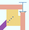
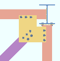
For a non-sloping horizontal brace, this is the elevation of: the top flange for a W tee ; neutral axis for an HSS ( round or rectangular ); leg to gusset for an L . Both ends of a non-sloping horizontal brace must be at the same elevation for connections to be designed.
In the examples below, the work point elevation determines whether the gusset plate fastens with clip angles to the webs of the beams ( left ) or bolts to the beam flanges ( right ).
|
Tip: To determine the end elevation on a horizontal brace while working in the 3D model: invoke a command like Construction Line Add , select EXPT as the Locate option, then move the point location target to the work point at the end of a horizontal brace and reference the Z coordinate reported in the X-Y-Z display .
Standard detail: None or the file name of a job standard detail or global standard detail .
If ' none ' is shown here, then no standard detail will be applied on this end of the horizontal brace when this brace is automatically detailed .
If a ' standard detail name ' is shown here, the next time automatic detailing of this brace is done in a full-featured SDS2 program , the reference point of the standard detail will align with the input work point on this end of the brace, and the standard detail's bill of material will be combined with the braces's bill of material. The detail is placed on a layer that is named after the standard detail plus a "_L" or "_R" suffix.
page 1 | contents | review | top
|
|
|||||||||
|
|
||||||||
Input connection type: User defined or Plain end or Hbrc plate .
' User defined ' means that the user defined connection file name that is entered to " User defined connection " has been or will be incorporated into the design of this connection in a full-featured SDS2 program .
' Plain end ' indicates that a connection has not or will not be generated on this end of the brace.
' HBrc Plate ' instructs connection design to automatically design a gusset plate based on the framing situation for this end of the brace.
Design of the " Input connection type " shown here takes place in a full-featured SDS2 program .
"
Connection specifications " and "
Connection design locks " provide settings for finer control of a connection's design..
The " Design Calc " or " Expanded Calc " button on this window gives you the connection's design calculations.
User defined connection: The file name of the user defined connection to be applied on this end of the horizontal brace.
This "
General settings " option applies when ' User defined ' is the " Input connection type ."
System designed connection: The type of connection designed on this end of the brace (e.g. ' Hbrc plate ' or ' Plain end ').
NM bolt type: Auto or A325N or A325SC or A325X , etc. NM stands for "non-moment."
If " Auto " is checked (
), connection design (in a full-featured SDS2 program ) creates the connection on this end of the brace using the " Default non-moment bolt type " set up under Job Options .
If " Auto " is not checked (
), connection design uses the type of bolt shown here for the connection on this end of the brace.
NM bolt diameter: Auto or a user-entered diameter .
| diameter |
|
If " Auto " is checked (
), connection design in a full-featured SDS2 program looks to the " Default non-moment bolt diameter for this job " set in Bolt Settings to determine the bolt diameter to be used for the connection on this end of the brace.
If " Auto " is not checked (
), connection design uses the bolt diameter shown here for the connection on this end of the brace.
Use miscellaneous plates list: ![]() or
or ![]() .
.
If this box is checked (
), connection design in a full-featured SDS2 program looks to Home > Project Settings > Fabricator > Standard Fabricator Connections > Plates to determine the plate thicknesses to be used for plates on the connection for this end of the brace.
If the box is not checked (
), connection design rounds the calculated required thickness of plates as based on the load to the next 1/16 inch (or 1/8 inch if the calculated required thickness is greater than 5/16 inch).
Related settings: " Design by first incrementing gusset thickness or size " (affects gusset thickness), " Minimum gusset thickness " (affects gusset thickness).
Minimum setup connection: Automatic or Yes or No . The Connection Design Calculations and Expanded Connection Design Calculations report the connection strength for various limit states regardless of the selection made here.
|
|
' Automatic ' instructs connection design in a full-featured SDS2 program to create the connection on this end of the brace based on the choice made to the " Minimum setup connection " field in Design Settings .
' Yes ' instructs connection design in a full-featured SDS2 program to create the connection on this end of the brace with the minimum number of bolt rows, the minimum gusset plate thickness, etc. A green banner in the "
Loads " leaf will notify you that the connection has been designed with the " Minimum setup connection capacity ."
' No ' instructs connection design in a full-featured SDS2 program to create the connection on this end of the brace to meet loading conditions derived from calculated values (Auto entries) or user-entered values made to "
Loads " on this window.
Disable framing situation checks: ![]() or
or ![]() . The choice made here does not affect this program. Framing situation checks are not done in SDS2 Site Planning.
. The choice made here does not affect this program. Framing situation checks are not done in SDS2 Site Planning.
If this box is checked (
), framing situation checks are turned off.
If the box is not checked (
), the framing situation checks are turned on.
page 1 | contents | review | top
|
|
|||||||||
|
|
||||||||
For more information, click a link :
| Gusset plate grade | Gusset to clip connection |
| Gusset cut | Gusset clips on |
| Use OS gusset holes | Clip angle size |
| Pipe/tube end fitting | Attach long leg to |
| Notch length clearance | Hole type supported |
| Erection bolts | Hole type supporting |
| Angle end fitting | Bolt type |
| Include end welds | Bolt diameter |
| Balanced welds | Stagger bolts |
| Clip end operation ( |
Supporting mem web stress |
| Gusset to beam connection |
page 1 | contents | review | top
|
|
|||||||||
|
|
||||||||
Field clearance: If this option is selected ( ![]() ), the user of a full-featured SDS2 program has probably set the distance between the end of the brace and the web (or flange) of the supporting beam. Or this may be the distance between the end fitting on the brace and the web (or flange) of the beam. Or it may the distance between the end of the brace and the edge of the clip angle that bolts the gusset to the beam's web.
), the user of a full-featured SDS2 program has probably set the distance between the end of the brace and the web (or flange) of the supporting beam. Or this may be the distance between the end fitting on the brace and the web (or flange) of the beam. Or it may the distance between the end of the brace and the edge of the clip angle that bolts the gusset to the beam's web.

|
fc = field clearance |
Status Display: Member status > Left end field clearance and Right end field clearance
Input minus dimension: If this option is selected ( ![]() ), the distance shown here was probably entered by a user of a full-featured SDS2 program . The minus dimension is distance from the end of the vertical brace to the work point for that end. Increasing the minus dimension makes the vertical brace shorter.
), the distance shown here was probably entered by a user of a full-featured SDS2 program . The minus dimension is distance from the end of the vertical brace to the work point for that end. Increasing the minus dimension makes the vertical brace shorter.
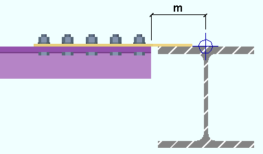
|
m = minus dimension |
Status Display: Member status > Left end minus dimension and Right end minus dimension
Automatic Minus dimension: If this option is selected ( ![]() ), then a full-featured SDS2 program calculates the minus dimension, taking into account the brace's " Brace to other member " clearance, " Minimum edge distance , " and the depth or flange width or web thickness of the supporting member.
), then a full-featured SDS2 program calculates the minus dimension, taking into account the brace's " Brace to other member " clearance, " Minimum edge distance , " and the depth or flange width or web thickness of the supporting member.
Status Display: Member status > Auto minus dimension (either end)
Status Display: Member status > Left end minus dimension and Right end minus dimension
page 1 | contents | review | top
|
|
|||||||||
|
|
||||||||
Warning : When Auto is not checked for a particular type of load, then the user of a full-featured SDS2 program has entered a load to that field. Users should make entries to load fields only at the direction of a qualified engineer.
| Minimum setup connection capacity |
| A banner like this one appears here if the connection on this end of the brace is a " Minimum setup connection ." |
Tension load (kips or kN): Auto or a user-entered load in kips (kilonewtons for ' Metric '). A tension load tends to stretch the member in the direction of its length. The load is used in design calculations for horizontal brace connections.
| Tension load: |
|
|
| or | ||
| Tension load: |
|
|
If " Auto " is checked (
), connection design in a full-featured SDS2 program calculates the tension load on this end of the member using the value entered to " Brace design tension. . . % of allowable load " in Design Settings . The calculated numerical value -- calculated in this example -- is the actual value that is used to design the connection on this end of the horizontal brace. Design method considerations: For ' ASD ' or ' LRFD ', the "
Auto " tension load is calculated per Section D2. For ' CSA 8 ' or ' CSA 9 ', it is calculated per Clause 13.2. For ' AS 4100 ', it is calculated per Clause 7.2.
If " Auto " is not checked (
), a user of a full-featured SDS2 program has set the load. The user-entered value is used to design the connection.
Status Display: Memberr status > Left end tension load and Right end tension load
Status Display: Connection auto loads > Auto horizontal brace tension
Compression load (kips or kN): Auto or a user-entered load in kips (kilonewtons for ' Metric '). A compression load tends to compress or shorten the member. The load is used in design calculations for horizontal brace connections.
| Compression load: |
|
|
| or | ||
| Compression load: |
|
|
If " Auto " is checked (
), connection design in a full-featured SDS2 program calculates the compression load on this end of the member using the value entered to " Brace design compression . . . % of allowable load " in Design Settings . The calculated numerical value -- calculated in this example -- is the actual value that is used to design the connection on this end of the horizontal brace. Design method considerations: For ' ASD ' or ' LRFD ', the "
Auto " compression load is calculated per Section E3. For ' CSA 8 ' or ' CSA 9 ', it is calculated per Clause 13.3. For ' AS 4100 ', it is calculated per Clause 6.3.
If " Auto " is not checked (
), a user of a full-featured SDS2 program has set the load. The user-entered value is used to design the connection.
Status Display: Member status > Left end compression load and Right end compression load
Status Display: Connection auto loads > Auto horizontal brace compression
page 1 | contents | review | top
|
|
|||||||||||
|
|
||||||||||
A left- and right-end " ![]() Summary " can be shown on this window only if you are editing one horizontal brace. There is no summary if you are editing multiple hroizontal braces.
Summary " can be shown on this window only if you are editing one horizontal brace. There is no summary if you are editing multiple hroizontal braces.
The "
Summary " leaf gives you a summary of connection information related to the left or right end of the horizontal brace.
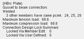
The summary shows (in parentheses) the " System designed connection ."
If other horizontal braces have been assigned the same piecemark as this horizontal brace, the summary lists those other horizontal braces by member number (24, 25, 26 in the example).
If this horizontal brace is part of a group member, the summary shows the group member piecemark .
The " Maximum tension load " and " Maximum compression load " show the capacity of the connection.
"
Connection design locks " and "
End preparations " that were locked (
) because the " Input connection type " is ' User defined ' are reported as " Locked Via User Defined ." All other locks that are locked (
) are reported as " Locked Via Member Edit ."
|
|
|||||||||||
|
|
||||||||||
Top flange operation : ' None ' or ' Cope plain ' or ' Cope field weld #3 (Standard) ' or ' Cope shop weld #3 (Standard) ' or ' Cut flange width ' or ' Cut flange flush ' or ' Clip flange ' or ' Notch ' or ' Notch NS/FS ' or ' Cope field weld #1 (FEMA) ' or ' Cope shop weld #1 (FEMA) ' or ' Clip web ' or ' Seismic cope field weld ' or ' Seismic cope shop weld '.
Bottom flange operation : same as above, except that this applies to the bottom flange.
page 1 | contents | review | top
|
|
|||||||||||||
|
|
||||||||||||
Status Display: Search > Connection design locks set
Search: Connection design locks set .
Design Calculations Report: Connection Design Lock SummaryThis documentation categorizes connection design locks by framing situation.
--- HBrc to a Beam's Top Flange --- HBrc to a Beam's Web --- perpendicular to Beam --- 2- and 3-point, to top flange or web
--- HBrc Intersection (x bracing) --- HBrc to a Beam-Beam Corner --- HBrc to a Bm-Col-Bm Corner Locked (
) connection design locks are entries made by users of a full-featured SDS2 program .
Unlocked (
) connection design locks are computer-generated values entered by connection design . In many cases, connection design populates the unlocked fields based on user-entered setup choices.
The limit state information tells you the capacity of the designed connection.
These same connection design locks may also be found (and revised) on the Connection Component Edit window for this connection.
When checked, "
Show images " lets you see drawings that depict the dimensions associated with connection design locks.
Connection design locks are grouped togetner under leaves with the following names:
Horizontal Brace to a Beam's Top Flange
|
Horizontal Brace to a Beam's Web
|
Horizontal Brace perpendicular to a Beam
|
Horizontal Brace Shared 'k' Connection (2- or 3-point bracing)
|
| Horizontal Brace Intersection (X bracing) |
| Horizontal Brace to Beam-Beam Corner |
| Horizontal Brace to Beam-Column-Beam Corner |
page 1 | contents | review | top
|
| ||||||||||||||
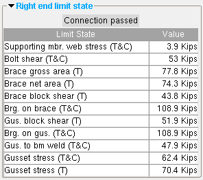 | These limit states are for an angle horizontal brace welded to the web of the supporting beam. The values shown represent the strength capacity of the connection or of the supported member (this horizontal brace) or the supporting member. In this example, the connection passes. (T) = tension (C) = compression |
A limit state is a potential connection failure mode.
The capacity of a connection is calculated for various limit states during connection design . Each " Value " reported in the example above represents the strength of the connection or of the beam itself or of its supporting member with respect to a particular limit state.
Since connection design takes place in a full-featured SDS2 program , but not in SDS2 Site Planning, the limit states that are reported on this review-only window are static and cannot be changed.
If connection design in a full-featured program has determined that the capacity of a connection is insufficient to stand up to the "
Loads " on the horizontal brace, or if there is a geometry problem related, for example, to the work points of the brace, the program will have failed the connection and generated a connection failure message such as:
Invalid brace work point location The Design Calculations Report together with the Connection Calculation Cover Sheet (or the Expanded Connection Design Calculations as a stand-alone report) provide formulas and the results of calculations (or the actual calculations) that relate limit states to the design of the specific connection.
page 1 | contents | review | top
Left end settings
Information
Member
Connection type
Connection specifications
Setbacks
Loads
Summary
End preparations
Connection design locks
Left end limit state
Components
Right end settings
Information
Member
Connection type
Connection specifications
Setbacks
Loads
Summary
End preparations
Connection design locks
Right end limit state
Components
The following custom components are distributed with SDS2 programs and may be applied to horizontal braces. You therefore can potentially find settings for them on the Horizontal Brace Review window:
HSS Cap Plates Custom component settings will be shown on this window after a custom component has been added to this horizontal brace in a full-featured SDS2 program .
Settings for custom components from outside distributors can also be reviewed on this window. However, since such custom components are not distributed with SDS2 programs, they are not documented in this help manual.
Tip: An alternative to reviewing a custom component on this window is to double-click material generated by that custom component in the model. The program will open a custom component review window that includes all the settings for that custom component, but does not include the other settings that can be found on the Horizontal Brace Review window.
page 1 | contents | review | top
"Properties" opens the Edit Properties window, on which you can make entries to custom properties . If, at the time it was created, your current Job was set to use a legacy flavor, the window that opens is named Custom Properties , not Edit Properties .
The Edit Properties window can also be used to read "
Log " entries or review or type "
Notes ."
Tip: Model > Member > Properties is an alternative to this button. It opens the Edit Properties window directly, without your first having to open a member review window.
" Status " opens the Member Status Review window for the horizontal brace(s) that you are reviewing. You can use that window to update status information about the horizontal brace(s).
" OK " (or the Enter key) closes the Horizontal Brace Review window (this window) and saves to the member file(s) any changes made on the Member Status Review window.
Change all: If you double-clicked a brace and made a change to its status and the 3D model contains other horizontal braces with the same piecemark as this brace, a yes-no dialog opens after you press " OK ." On that yes-no dialog is the question, " Do you want to change all .... " Press the " Yes " button to update the status of all the horizontal braces with this piecemark; press the " No " button to change only this one brace.
Tip: The yes-no "change all" dialog tells you the count of the members with this " Piecemark ." Another way to find out the count of members under the piecemark is to look under the "
Summary " on this window.
" Cancel " (or the Esc key) closes this window without saving any status changes made on the Member Status Review window.
" Reset " undoes all status changes you made to this member on the Member Status Review window.
"Design Calc" outputs a report that includes this brace's design calculations, general settings and left/right end settings. If you are reviewing multiple braces with the same piecemark (or different piecemarks), you get a report for each brace. Each report is output to the destination specified at User and Site Options > Output > " Reports ."
calcs Tip: To get a report listing similar specifications for multiple members, output a Check Report and a Design Calculations Report .
"Expanded Calc" outputs the Expanded Connection Design Calculations . Output is to your web browser.
Expanded Connection Design Calculations is a report that provides all of the information in the Connection Design Calculations combined with related information from the Connection Calculation Cover Sheet . In addition, the report shows you the calculations written out, in detail, in the report itself, instead of simply reporting the results. Certain browser requirements must be met in order for you to access this report.
If you are reviewing multiple horizontal braces with the same piecemark (or different piecemarks), you get a report for each brace.
Connection design failures can be found with the aid of a search or by a quick scan of the document. Calculations that result in a connection failure are identified as " (NO GOOD) " in their concluding line. You might also search for the string "CONNECTION DESIGN FAILURE".

