Bent Plate Connection ("  Connection specifications " and more)
On this page :
- Information:
- Connection specifications:
- Locks:
Setup of bent plates :
- Standard Bent Plate Settings (C/C gages, etc.)
- Plates (setup window sets default grade by connection type)
- Top of Steel to First Hole ( Schedule of Minimums )
- Schedule of Minimums (number of bolt rows and diameters)
- Bolt spacing (vertical spacing between rows, per bolt diameter)
- Available bolt sizes (when connection design increments diameters)
- Amount of allowable k infringement (placement)
- Field clearance (non-auto standard)
- Field clearance (auto standard)
Also see :
- Status Display ( Connection type > Bent plate )
user defined | auto standard | beam | system
General info about bent plate connections :
The " Moment type " for a bent plate connection can be ' Non-moment ' or ' Bolted ' or ' Welded '. Supported framing conditions for bent plate moment connections are essentially the same as those framing conditions that are supported for moment clip angles. Skewed framing conditions for bent plate moment connections are not supported.
1) Wide flange beam to wide flange column web or flange with bolted moment plates, bent plate connection (beam perpendicular to column);
2) Wide flange beam to wide flange column flange with welded moment plates, bent plate connection (beam perpendicular to column);
3) Wide flange beam to wide flange column web or flange with bolted moment plates, bent plate connection (beam perpendicular to column, and beam and column have the same elevation);
4) Wide flange beam to wide flange column flange with welded moment plates, bent plate connection (beam perpendicular to column, and beam and column have the same elevation);
5) Wide flange beam to wide flange beam with the third wide flange beam on the opposite, with bolted moment plates, bent plate connection;
6) Wide flange beam to wide flange column flange with bolted moment angles, bent plate connection (beam perpendicular to column);
7) Wide flange beam to wide flange column web or flange with bolted moment plates, bent plate connection (beam to column with slope).
Connection design in a full-featured SDS2 program is able to create non-moment bent plates on the ends of wide flange or channel beams under beam-to-beam or beam-to-column framing conditions. The supported beam can be skewed or sloped or framed perpendicular into a wide flange or HSS rectangular column, but not an HSS round column.
Bent plates are applied on the end of the supported beam , but may optionally be designated to be detailed with (and therefore attached to) the supporting member. If framing into a tube column, the bent plate must be shop welded to the supporting column.
Non-moment bent plates are often applied in situations where it is impractical to use a clip angle connection -- for instance, in skewed framing situations. Connection design will produce bent plates from 56 to 90 degrees for two-sided connections and from 18 to 90 degrees for one-sided connections.
In a full-featured SDS2 program , connection design will look to relevant setup selections and bent plate type specifications when it creates the bent plate. If necessary to meet loading conditions, the program will increase rows of bolts and bolt diameter and plate thickness to design a connection that works. If The program cannot use a bent plate in a particular situation, The program will attempt to design a shear plate connection at that framing situation.
user defined | auto standard | beam | system | top
------ " ![]() Connection specifications " for beam ' Bent plate ' connections ------
Connection specifications " for beam ' Bent plate ' connections ------
|
" |
|
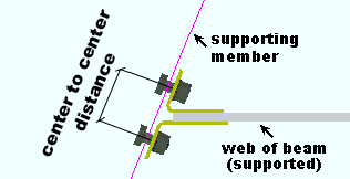
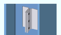
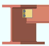
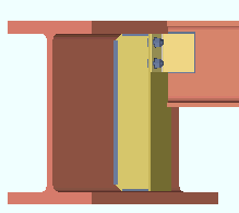
A bent plate connection's gage is the center-to-center distance from the column of holes on the one bent plate to the column of holes on the other bent plate. ' Narrow ' and ' Wide ' gages can be defined in setup. |
In a full-featured SDS2 program . . .
' Narrow ' specifies that a narrow gage bent plate connection be designed per the distance entered to Home > Project Settings > Fabricator > Standard Fabricator Connections > Bent Plate Settings > " Center to center distance, narrow gage ."
' Wide ' specifies that a wide gage bent plate connection be designed per the distance entered to Home > Project Settings > Fabricator > Standard Fabricator Connections > Bent Plate Settings > " Center to center distance, wide gage ."
Attachment to supported: Bolted or Welded . The supported member is the beam. The bent plate's leg to supported attaches to the web of that beam. This " ![]() Connection specifications " option can be found on that beam's edit window or on the setup windows for auto standard or user defined connections.
Connection specifications " option can be found on that beam's edit window or on the setup windows for auto standard or user defined connections.
|
|
In a full-featured SDS2 program . . .
' Bolted ' specifies that the connection be bolted to the beam's web. The bolts may be field bolts or shop bolts depending on the choice made to " Attached to . " If " Attached to " is ' Supported ,' the bent plate shop bolts to the beam's web. If " Attached to " is ' Supporting ,' the bent plate field bolts to the beam.
' Welded ' specifies that the bent plate be welded to the beam's web. Whether the welds are shop welds of field welds depends on the choice made to " Attached to ." If " Attached to " is set to ' Supported ', the bent plate shop welds to the supported beam. If " Attached to " is ' Supporting ', the bent plate field welds to the beam.
Conn changed. Possibly: Bent plate vs Shear tab 
connection changed banner Connection design cannot create a bent plate whose " Attachment to Supported " and " Attachment to Supporting " are both set to ' Welded '. Most likely the program will, instead, design a shear plate connection and notify you of such with a connection changed banner like the one shown above. When such a banner is emitted, the " System designed connection " for this end of the beam is reported to be a ' Shear plate '.
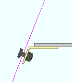
Attachment to supporting: Bolted or Welded . The supporting member is the beam or column that the outstanding leg(s) of the beam end's single or double bent plate connection attaches to.
|
|
In a full-featured SDS2 program . . .
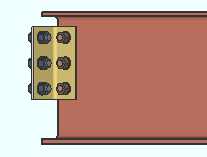
' Bolted ' specifies that connection design create a bent plate connection that bolts to the supporting member (beam or column). If " Attached to " is ' Supporting ,' the bent plate shop bolts to the supporting member. If " Attached to " is ' Supported ,' the bent plate field bolts to the supporting member. In the above, left example, the connection is shop bolted to the supporting member (the column) and field bolted to the supported beam.
' Welded ' instructs connection design to create a bent plate that shop welds to the supporting beam or column. If " Attached to " is ' Supporting ,' the bent plate shop welds to the supporting member. If " Attached to " is ' Supported ,' the bent plate field welds to the supporting member.
Conn changed. Possibly: Bent plate vs Shear tab connection changed banner Connection design cannot create a bent plate whose " Attachment to Supported " and " Attachment to Supporting " are both set to ' Welded '. Most likely the program will, instead, design a shear plate connection and notify you of such with a connection changed banner like the one shown above. When such a banner is emitted, the " System designed connection " for this end of the beam is reported to be a ' Shear plate '.
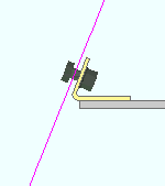
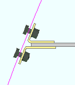
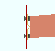
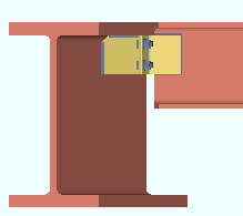
Side: Near side or Far side or Both .
' Near side '
 |
' Far side '
|
' Both '
|
In a full-featured SDS2 program . . .
' Near side ' or ' Far side ' specifies a single bent plate fastened to the designated side. The near side is the web of the beam on which the left end of the beam is to your left and the right end of the beam is to your right.
' Both ' specifies double bent plates: one fastened to the near side web of the supported beam, the other to the far side web.
Attached to: Supported or Supporting .
' Supported '
|
' Supporting '
|
In a full-featured SDS2 program . . .
' Supported ' specifies that the bent plate connection be attached (welded or bolted) in the shop to the supported member (beam). It will be considered to be a submaterial of that beam and will therefore appear on details of that beam and in that beam's bill of material. A " Field clearance " can be applied.
' Supporting ' specifies shop attachment to the supporting member (beam or column).
Stagger on: Nonstaggered or Supporting or Supported . This " ![]() Connection specifications " option applies to bent plates that are bolted in both legs.
Connection specifications " option applies to bent plates that are bolted in both legs.
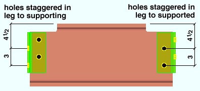
In a full-featured SDS2 program . . .
' Nonstaggered ' specifies that connection design create the bent plate with identical vertical hole spacing in both legs of the plate.
' Supporting ' specifies normal vertical hole spacing in the leg to the supported beam and a staggered hole pattern in the leg to the supporting member.
' Supported ' specifies normal vertical hole spacing in the leg to the supporting member and a staggered hole pattern in the leg to the supported beam.
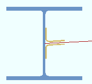
Welded extended tee: ![]() or
or ![]() . This "
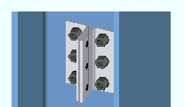
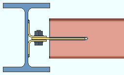
. This " ![]() Connection specifications " option can apply to a beam with a bent plate connection framing perpendicular or sloping or skewed (as shown below) to a supporting beam.
Connection specifications " option can apply to a beam with a bent plate connection framing perpendicular or sloping or skewed (as shown below) to a supporting beam.
 |
 |
| The tee face that the bent plate connects to in the left example is parallel to the beam web. | |
In a full-featured SDS2 program . . .
If this box is checked (
), connection design generates a built-up tee (two plates welded together) for the connection to bolt to. The check box for " Full depth extended tee " under certain framing situations controls whether the tee is designed to the depth of the connection or to the full depth of the supporting beam.
If the box is not checked (
), connection design bolts the bent plates to the supporting beam's web.
Full depth extended tee: ![]() or
or ![]() . This applies when the box is checked here -- in "
. This applies when the box is checked here -- in " ![]() Connection specifications " -- for " Welded extended tee ."
Connection specifications " -- for " Welded extended tee ."
 |
 |
In a full-featured SDS2 program . . .
If this box is checked (
If the box is not checked (
Bent plate grade: Auto or user selected .
In a full-featured SDS2 program . . .
'
'
). Choices shown in that list box come from Home > Project Settings > Job > Plate Grades .
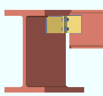
Use paddle plate: ![]() or
or ![]() . This "
. This " ![]() Connection specifications " option applies when an HSS/TS beam frames to a wide flange or S shape column. It permits the design of bolted-bolted or bolted-welded bent plates. The option is disabled ( grayed out ) when the bent plate's " Attachment to supported " is ' Welded ' and " Attached to " is ' Supported .'
Connection specifications " option applies when an HSS/TS beam frames to a wide flange or S shape column. It permits the design of bolted-bolted or bolted-welded bent plates. The option is disabled ( grayed out ) when the bent plate's " Attachment to supported " is ' Welded ' and " Attached to " is ' Supported .'
|
|
In a full-featured SDS2 program . . .
If this box is checked (
If this box is not checked (
user defined | auto standard | beam | system | top
Connection design locks for bent plates :
Connection design locks for bent plate connections may appear, under a leaf with one of the below-listed names, on the Beam Review window or on a Connection Component window. The locks can also appear on the User Defined Connections window.
| Connection Design Locks
(" Input connection type " = ' Bent plate ') |
|
| Leaf Name | Situation |
| Bent Plate | The near side plate and the far side plate can be adjusted independently. |
| Beam Web Doubler |
Beam web doublers are designed for beam-to-beam framing situations when required. When they are not required, " |
| Welded Tee | Connection design can create a built-up tee for beam-to-beam framing situations instead of bolting the bent plate to the supporting beam's web. |
| Safety Seat |
May be applied for non-moment bent plates in beam-to-column framing situations. Under " |
| Top Moment Plate Bottom Moment Plate |
Under " |
| Moment Cap Plate | A beam with a welded moment connection to the top of a column flange. The moment cap plate shop welds to the column. |
| Column Web Doublers
Column Flange Stiffeners |
The boxes for " |
| Top Moment Angle Bottom Moment Angle | The " Connection material " specified must be angle and suitable angle material must be available. |
user defined | auto standard | beam | system | top