 Display Center of Mass and Weight
- Step-By-Step
- Tips and Tricks
- Related Tools
1 . Preselect a Member to enable the Members contextual page and click the Display Center of Mass and Weight icon found in the Tools section.
Alternative: Invoke Display Center of Mass and Weight using the Find Tool by searching the command name and clicking the icon, which is pictured above.
Learn more about alternative methods for launching commands.
2 . The status line prompts, "Locate reference point". Left-click (Locate) a reference point the center of mass will be measured from.
Alternative 1: Press Esc or right-click (Return) to not add a reference point. The center of mass will be measured from the 0,0,0 global coordinate.
Alternative 2: If you did not preselect a member, the status line prompts, "Select members". Left-click (Locate) to select one or more members. Press Enter or right-click (Return) and select OK. Then follow step 2 above. Alternatively, press Esc or right-click (Return) to end the command.
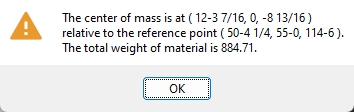
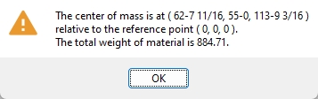
3 . An OK dialog opens. It reports the center of mass and total weight of the selected members. Press OK to close the window and end the command.
|
Possibility 1 : If you located a reference point in step 2, the center of mass is reported with respect to that reference point. |
|
Possibility 2 : If you did not locate a point in step 2, the center of mass is reported with respect to the 0, 0, 0 global coordinate. |
- Global coordinates (center of mass point is reported in)
- Report Writer (can output weight and center of mass of individual members)

