Status Display ( Modeling > Shift + ? )

Tool summary :

  • Opens the Status Display window, on which you can define conditions that color code, isolate or hide members, materials and other items based on their attributes.
  • Status Display conditions for members can affect the display of members in stick . For conditions that apply to materials, bolts, holes and welds, members need to be styled as solid .
  • A status condition is true when it is able to color-code an item in the model.
  • See invocation and tips .

Also see :

page 1 | contents | status display (opens with this tool) | status (index)


Opening Status Display and tips on using the window :

1 . Invoke Status Display using any one of the following methods:

Method 1 : Click the Status Display icon, which is pictured above. The icon can be taken from the group named ' Model ' and placed on a toolbar (classic) or the ribbon (lightning).

Method 2 : If " Modeling layout style " is ' Classic ', you can use the menu system to choose Model > Status Display .

Method 3, 4 or 5 : Status Display can also be configured to be invoked using a keyboard shortcut , the context menu , or a mode . For the lightning interface, this configuration is done using Customize Interface .

Method 6 : Check the box for " Set the status display criteria " on the window that opens when you Detail Erection Views and press the " Settings " button.

Tip: To start off with a single " Priority " (and a default condition), press the " Clear " button.

2 . The Status Display window opens. Here are some tips for setting the status display:

Basics:

  • Press the " OK " button to close this window and activate status display in the model.
  • To close this window and deactivate status display in the model, press the " Cancel " button.
  • To temporarily activate status display in the model without closing the window, press the " Apply " button.
  • If you are opening this window for the first time in a Modeling session, the files selected for User and Site Options > Modeling > " Status display criteria " are shown. Any changes you make on this window are remembered during your Modeling session. However, the originally loaded status display files will not be changed unless you choose to overwrite them.

Saving files:

  • You can save a status display file that is shown on this window (that file only) by pressing the " Save " icon ( ) that is embedded in the file name banner for that file.
  • You can press the " Save " button at the bottom of this window to save all of the status display files that are shown on this window.
  • If User and Site Options > Modeling > " Prompt to save status display after changes " is on ( ), then pressing " OK " at the bottom of this window will give you prompting to save (or not save) changes to each file that you changed on this window.

Opening and closing files:

  • If you make changes to this window then reopen it, you will find that the window has remembered the changes you made. If you want just a one file with one priority and a default condition, you can press the " Clear " button.
  • Click the " Load " button (at the bottom of this window) to open the conf_status folder, in which you will find a number of status display files. " Load " can be used to open more than one file.

Beyond the basics:

VIDEO

Status Display sets existing members (a concrete wall) as masked, that is, not visible. " Show item as " is then set to a cyan color and " Apply " is pressed, causing the concrete wall to be displayed. Then " Show item as " is set back to 'M asked ' and " Apply " is pressed, causing the concrete wall to disappear again. The Status Display user interface has changed since this video was made. (Recorded in SDS2 Site Planning , v7.3.)

  • More than one color can be applied. Each different color must be in its own priority . Each priority must have at least one condition .

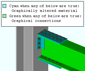
The " Legend " in this example shows two priorities, each with one condition. Priority 1 uses cyan to color code " Graphically altered members ." Priority 2 uses green to color code " Graphical connections ." The clip angle and moment flange plates would be green if the order of priority were reversed

  • Where multiple conditions are true for one member, the conditions in the higher priority (lower number) apply. This means, for example, if priority 1 makes members red and priority 2 makes some of those same members blue, the members found to be true by both priority 1 and priority 2 are red. Within a status display file, priority 1 is always listed first, with priority 2 is second, and so on.

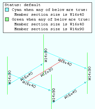
The " Legend " in this example shows two priorities. Priority 1 displays in cyan and is listed 1st. Priority 2 displays in green. Although section sizes W16x40 are in both priorities, cyan is the color applied in the model to W16x40 members because, in this example, cyan is specified in the higher priority.

  • If you want the selected " Priority " to not apply to members or materials, check the box for " Disable ." To add a new priority, press the " New Priority " ( ) button.
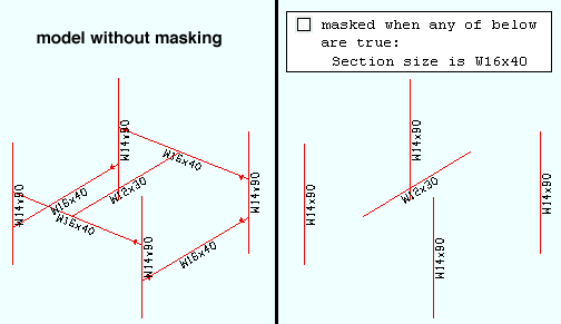
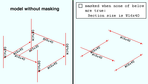
  • Status Display can mask members ( mask + any ) or isolate them ( mask + none ) as well as color code them or -- if they are solid -- make them translucent.
Compare this example with the example below. In this example, the selection of any results in W16x40 members being masked.

This example does the opposite of the example above. In this example, the selection of ' none ' results in W16x40 members being isolated from all other members that are shown in the view.
  • Putting conditions in different priorities lets you to color code different items in different colors. In the following example, the items that are color coded are members (priority 2) and welds (priority 1) Be aware, though, that the order of the priority can make a difference to status display, as you would quickly discover if you were to create the following example then use the button to " Move Up " priority 2 so that it becomes priority 1.
The Priority 2 condition color codes (cyan) those members that have at least one field weld. The Priority 1 condition color codes red the field welds themselves. Switching the order of these priorities would give different results. If the priority 2 condition were to be made priority 1, the field weld would not be red -- it would be cyan along with the member.
  • Sometimes it is useful to put condition ranges in different priorities so that different display logic can be applied to each range. " Material plate thickness " (with different ranges) is used for both priorities in this example.
1/2 inch plates are included in both ranges in this example. Since priority 1 takes precedence, 1/2 inch plates will be displayed in the color cyan (not as orange).
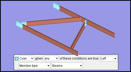
  • You can select ' Member ' or ' Ends ' or ' Left ' or ' Right ' as the item to be color coded . The option ' Ends ' is especially useful for conditions that are true for members that have a particular left/right end setting. For example, you could specify a " Failed connection " condition that color codes member ends with failed connections. ' Member ' is the safest option if you are in doubt about which option is best for a particular condition.
This example of a status display condition color codes beam left ends in the color cyan .

page 1 | contents | status display (opens with this tool) | status (index) | top