Status Display & Status Select
- Status Options
- Screen Widgets
- Tips and Tricks
- Related Tools
General status options
Is / is not from a zone to a zone. The same zone twice (e.g., 1 to 1 ) designates a single zone.
To enter a zone range: press the ![]() browse button to open a list of zones that have been defined on the Zone Names window in setup. On the list, select the range of zones that you want. After you press OK to close the list, From and To is filled out with the first and last zones that you selected.
browse button to open a list of zones that have been defined on the Zone Names window in setup. On the list, select the range of zones that you want. After you press OK to close the list, From and To is filled out with the first and last zones that you selected.
Setup: Zone and Sequence window
Tools: Update Attributes , Sequence By Area
Status Report by XXX: Zone
Report Writer: Member.ErectionZone
Advanced Selection: ErectionZone
Parametric module: ErectionZone
Is / is not from a sequence to a sequence. The same sequence twice designates a single sequence (e.g., 2 to 2 ).
To enter a sequence range, press the ![]() browse button to open a list of sequences that have been defined at Home > Project Settings > Job > Modeling > Zone and Sequence > press Sequence Names . On the list, select the range of sequences that you want. After you press OK to close the list, From and to is filled out with the first and last sequences that you selected.
browse button to open a list of sequences that have been defined at Home > Project Settings > Job > Modeling > Zone and Sequence > press Sequence Names . On the list, select the range of sequences that you want. After you press OK to close the list, From and to is filled out with the first and last sequences that you selected.
Member edit windows: Sequence
Setup: Zone and Sequence screen
Tools: Update Attributes , Sequence By Area
Status Report by XXX: Sequence
Report Writer: Member.ErectionSequence
Advanced Selection: ErectionSequence
Parametric module: ErectionSequence
Is / is not from a number to a number. This option is for tracking member revisions, not sheet revisions. It can track any range of Short revision descriptions that are currently assigned to members. The same number twice (e.g., 1 to 1 ) designates a single line number in Member Revisions settings. The first line in Member Revisions setup is line 0. A number entered here also corresponds to the order (beginning with 0) that a revision is listed on the list box ( ![]() ) for Short revision description in Member Status Review .
) for Short revision description in Member Status Review .
Tip: To color code those members that users have assigned a revision to, enter is not from 0 to 0. This works because 0 is the default revision, and users must select a revision other than 0 to have that other revision assigned.
Setup: Member Revisions
Member Status Review: Short revision description
Status Update: Revision
Reports: Member Revisions by Member , Members in Member Revisions
Status Report by XXX: Revision level
Sheet revisions: revision chart on a detail sheet
Parametric member module: mem1.RevisionLevel
When Yes is selected, the condition is true for members that a user has put On hold. A user can put a member On hold using Update Attributes or the Member Status Review window. Holding a member is usually interpreted as meaning holding a member's detail from release to the shop.
When No is selected, the condition is true for members that are not on hold.
Status Update: Member hold status
Member Status Review: Member hold status
Status Report by XXX: Member hold status
Report Writer: Member.MarkedForHold
Any string of characters. Text case does not matter (e.g., under review is interpreted as being the same as UNDER REVIEW).
Status Update: Reason for member hold
Member Status Review: Reason for member hold
Status Report by XXX: Member hold status
Report Writer: Member.DescriptionOfHold
When Yes is selected, the condition is true for any member that has been marked as an Existing member. Existing members are members that exist in the 3D model but are not to be fabricated. Members that are marked as existing can undergo Process and Create Solids but cannot be detailed, nor will they be included on any reports that have to do with cataloging or ordering materials for fabrication purposes. If a bolt is on an existing member and does not bolt to a non-existing member, it is excluded from reports. Automatic connections can be generated on existing members and on members framing into existing members.
When No is selected, the condition is true for members that are not marked Existing member. All members are not existing by default. To mark a member as existing, a user can use Update Attributes or Member Status Review .
Status Update: Existing member
Member Status Review: Existing member
Report Writer: Member.Conditions.IsExisting
Advanced Selection: IsExisting
Parametric module: IsExisting
A member piecemark . Only one piecemark can be entered. Text case does not matter (e.g., b_4 is interpreted as being the same as B_4 ).
Display Options: Member piecemarks
Advanced Selection: Piecemark
Parametric module: Piecemark
Status Display: Member status > Member piecemark (multi-select)
Detailing and processing
This applies mainly when User and Site Options > Modeling > Process within member edit is turned off and Automatically process after modeling operation is set to Do nothing.
When Yes is selected, the condition is true for members that have not yet undergone any phase of Process and Create Solids or, have been marked for processing. Since automatic processing takes place for processable members as they are added or edited, you will find that it is fairly unusual for members to be marked for all phases of Process and Create Solids.
When No is selected, the condition is true for members that are not marked for processing.
Member edit windows: Marked for processing
Hide Items: Process required
Report Writer: Member.LeftEnd.MarkedforProcess
When Yes is selected, the condition is true for members that have not yet undergone the Create Solids phases of Process and Create Solids . When User and Site Options > Modeling > Automatically process after modeling operation is set to Process or Do nothing, you will find that members will more commonly still require Create Solids .
When No is selected, the condition is true for members that are not marked for Create Solids .
Report Writer: Member.Conditions.MarkedforCreate3d
Advanced Selection: MarkedForCreate3d
Parametric module: MarkedForCreate3d
When Yes is selected, the condition is true for members, including group members , whose details have not yet been created or which have been modified in the 3D model since the time that their details were created. To change the needs to be detailed status of such a member, Detail Members .
When No is selected, the condition is true for members that have undergone Detail Members and which have not been altered since the time that they underwent Detail Members .
Hide Items: Detail required
Member edit windows: Marked for detailing
Report Writer: Member.Conditions.Markedfordetail
Advanced Selection: MarkedForDetail
Parametric module: MarkedForDetail
This applies mainly when User and Site Options > Modeling > Process within member edit is turned off and Automatically process after modeling operation is set to Do nothing.
When Yes is selected, the condition is true for members that have not yet been piecemarked. To change the Needs to be piecemarked status of such a member, Process and Create Solids .
When No is selected, the condition is true for members that have been assigned piecemarks.
Advanced Selection: MarkedForReAssignPiecemark
Parametric module: MarkedForReAssignPiecemark
When Yes is selected, the condition is true for members whose details have been placed onto detail sheets and to members that are part of any group member that has been placed onto a detail sheet.
When No is selected, the condition is true for any member whose detail has not yet been placed onto a detail sheet. The condition is also true for members that have no details. To change the status of such a member, you can use Detail Sheet Autoloading or Sheet Item Add to place the detail of the member onto a sheet.
Drawing Data Panel: On sheet
Hide Items: On sheet
Report Writer: Member.Conditions.detailIsPlacedOnDetailSheet
Advanced Selection: DetailIsPlacedOnDetailSheet
Parametric module: DetailIsPlacedOnDetailSheet
This Status Display option tracks printing of members on sheets using Plotting . It does not track members that have been printed using Home > Export > 2D > Export PDF Drawings .
When Yes is selected, the condition is true for members whose details have been placed onto a detail sheet and been printed.
When No is selected, the condition is true for members whose details have not yet been printed. To change the status of a member whose detail has not yet been printed, Plot the sheet on which that member's detail has been placed.
Drawing Data Panel: Last printed
Status Report by XXX: Last printed
Report Writer: Member.Conditions.MarkedForPlot
Advanced Selection: MarkedForPlot
Parametric module: MarkedForPlot
When Yes is selected, the condition is true for members whose main material has been altered by the user. On the General Information window of the main material you will find that the material is tagged as User modified main member material. All miscellaneous member materials that are ![]() Main member material
Main member material
When No is selected, the condition is true for members that do not have graphically altered main material.
Report Writer: Member.Conditions.MarkedAsGraphicallyAltered
Advanced Selection: MarkedAsGraphicallyAltered
Parametric module: MarkedAsGraphicallyAltered
Member must be selected in order to permit this option to color code materials. This option does not work when Ends or Left or Right is selected as the item to be color coded.
When Yes is selected, the condition is true for system connection material that has been made graphical . On the General Information window for graphically altered material, you will find that the material is tagged as User modified connection material. Under the "![]() Information " leaf on the edit windows of members that have graphically altered connection material, you will find that the box for
Information " leaf on the edit windows of members that have graphically altered connection material, you will find that the box for ![]() Graphical is checked:
Graphical is checked:
When No is selected, the condition is true for materials that are not graphically altered system connection materials.
Material display: This condition affects the display of material. Members must be displayed in one of the three solid forms in order for you to color code materials. Also, Member must be selected as part of the display logic for this condition.
Topic: Graphical connections
Change Options: Change Graphically Altered to System Connections
This applies to the member types beams, columns, vertical braces, horizontal braces, girts, purlins, stairs. It does not apply to miscellaneous members.
When Yes is selected, the condition is true for non-miscellaneous members whose main material has holes that were added using Add Holes . Matched holes generated during Create Solids or Match Holes are not user holes. To change the status of the member, you need to delete the holes.
When No is selected, the condition is true for members whose main materials do not have user-added holes.
When Yes is selected, the condition is true for material that has been added using Add Miscellaneous Member , Add Material , Copy Material , Add Assembly or Run Parametric .
When No is selected, the condition is true for system connection material. That is, it is true for material generated during Create Solids , for example, when beams, columns and braces were added or edited.
Member must be selected in order to permit this option to color code materials. This option does not work when Ends or Left or Right is selected as the item to be color coded.
When Yes is selected, the condition is true for members that have been assigned user piecemarks or which have not yet been assigned any piecemark.
When No is selected, the condition is true for members that have automatically been assigned piecemarks in the last phase of Create Solids .
Advanced Selection: SystemPiecemark
Parametric module: SystemPiecemark
Hide Items window: User assigned piecemarks
Modeling and Drawing Editor: Change User Piecemarks to System
Modeling and Drawing Editor: Change System Piecemarks to User
Approval and modeling
Is / is not from a date to a second date. ***Not Set*** is also a valid entry -- see entering dates .
Note: Process and Create Solids cannot change a member that has its Model complete date set, nor can it generate connections on members that frame to such a member. Materials , bolts , welds and holes cannot be added to, copied to, deleted from, or changed on the member. The member cannot be erased or deleted. All settings on the member's edit window become read-only ( disabled ).
Status Update: Model completed
Member Edit Window: Model complete date
Search: Frames to Model Complete
Hide Items: Model complete
Status Report by XXX: Model complete
Report Writer: Member.DateModelCompleted
Is / is not from a date to a second date. ***Not Set*** is also a valid entry -- see entering dates .
Note: Setting a detail complete date prevents a drawing from being automatically detailed . Users can Save changes made in the Drawing Editor to a drawing designated as complete, but to do so they need to override the detail complete date. A detail complete date can be assigned to a group member as well as to a member.
Hide Items: Detail complete
Drawing Data Panel: Detail complete
Status Update: Detail complete
Other ways to set: Drawing List Panel and Exit
Status Report by XXX: Detail complete
Report Writer: Member.DateDetailCompleted
Status Display (for materials): Material status > Material detail complete date
The check box found on the [ Left end settings ] banner of a member's edit window can be used to lock/unlock that member's left end .

When Yes is selected, the condition is true for members that have their [ Left end settings ] locked ( ![]() ) on their edit window ( Beam or Column or Horizontal Brace or Vertical Brace or etc.).
) on their edit window ( Beam or Column or Horizontal Brace or Vertical Brace or etc.).
When No is selected, the condition is true for members that have their [ Left end settings ] unlocked ( ![]() ) .
) .
A column member's left end is its bottom end. The check box for locking the left end of a column is found on the column edit window's [ Bottom end settings ] banner.
Status Update: Lock left/right end
Model complete: Lock Ends on Model Complete Members
The check box found on the [ Right end settings ] banner of a member's edit window can be used to lock/unlock that member's right end .

When Yes is selected, the condition is true for members that have their [ Right end settings ] locked ( ![]() ) on their edit window ( Beam or Column or Horizontal Brace or Vertical Brace or etc.).
) on their edit window ( Beam or Column or Horizontal Brace or Vertical Brace or etc.).
When No is selected, the condition is true for members that have their [ Right end settings ] unlocked ( ![]() ) .
) .
A column member's right end is its top end. The check box for locking the right end of a column is found on the column edit window's [ Top end settings ] banner.
Status Update: Lock left/right end
Model complete: Lock Ends on Model Complete Members
Member piecemark frozen : 
Member piecemark not frozen : 
When Yes is selected, the condition is true for members with frozen piecemarks.
When No is selected, the condition is true for members whose piecemarks are not frozen.
Tools: Freeze Piecemark , Thaw Piecemark
Status Update: Piecemark status (can be set to Freeze or Thaw )
Member edit windows: Frozen piecemark , Piecemark group
Also see: Frozen piecemarks (topic)
Member detail frozen : 
Member detail not frozen : 
When Yes is selected, the condition is true for members that have a Detail frozen date set on the Drawing Data Panel in the Drawing Editor.
When No is selected, the condition is true for members whose details have **NOT SET** as their entry to Detail frozen on the Drawing Data Panel. The condition is also true for members that have no details.
Drawing Data Panel: Detail frozen
Status Update: Detail frozen date
Is / is not from a date to a second date. ***Not Set*** is also a valid entry -- see entering dates .
Status Update: Submitted for approval
Member Status Review: Submitted for approval
Status Report by XXX: Submitted for approval
Report Writer: Member.SentForApprovalDate
Is / is not from a date to a second date.
Status Update: Received from approval
Member Status Review: Received from approval
Status Report by XXX: Received from approval
Report Writer: Member.DateReceivedApproval
Approved or Approved as noted or Resubmit or Rejected or Not reviewed.
Status Update: Approval status
Member Status Review: Approval status
Status Report by XXX: Approval status
Report Writer: Member.ApprovalStatus
Fabrication status
Is / is not from a date to a second date. ***Not Set*** is also a valid entry -- see entering dates .
Status Update: Projected for fabrication
Member Status Review: Projected fabrication complete
Status Report by XXX: Projected for fabrication
Report Writer: Member.ProjectedDateToShop
Is / is not from a date to a second date. ***Not Set*** is also a valid entry -- see entering dates .
Is / is not from a date to a second date. ***Not Set*** is also a valid entry -- see entering dates .
Status Update: Released for fabrication
Member Status Review: Released for fabrication
Status Report by XXX: Released for fabrication
Report Writer: Member.ActualDateToShop
Is / is not from a date to a second date. ***Not Set*** is also a valid entry -- see entering dates .
Status Update: Fabrication complete
Member Status Review: Fabrication completed
Status Report by XXX: Fabrication complete
Report Writer: Member.DateFabricationCompleted
When Yes is selected, the condition is true for members whose Fabrication complete date is less than its Projected for fabrication date.
When No is selected, the condition is true for any member whose Fabrication completed date is greater than its fabrication Projected for fabrication date.
Status Report by XXX: Fabrication completed on time
Shipping and erection status
Is/ is not from a date to a second date. ***Not Set*** is also a valid entry -- see entering dates .
Status Update: Projected to ship
Member Status Review: Projected shipped date
Status Report by XXX: Projected to ship
Report Writer: Member.ProjectDateToShip
Is / is not from a date to a second date. ***Not Set*** is also a valid entry -- see entering dates .
Status Update: Actually shipped
Member Status Review: Actual ship date
Status Report by XXX: Actually shipped
Report Writer: Member.ActualDateShipped
When Yes is selected, the condition is true when a member's shipping schedule has been met. A member's shipping schedule is met when its Shipping actual date is less than its Shipping projected date.
When No is selected, the condition is true when a member's shipping schedule has not been met. A member whose shipping schedule has not been met is any member whose Shipping actual date is greater than its Shipping projected date.
Status Report by XXX: Shipped on time
Is / is not from a date to a second date. ***Not Set*** is also a valid entry -- see entering dates .
Status Update: Received on job site
Member Status Review: Received on job site
Status Report by XXX: Received at jobsite
Report Writer: Member.DateReceivedAtJobsite
Is / is not from a date to a second date. ***Not Set*** is also a valid entry -- see entering dates .
Status Update: Erected
Member Status Review: Erected
Status Report by XXX: Erected
Report Writer: Member.DateErected
When you select a particular crane (placement), the condition reported becomes Members assigned to be lifted by crane at (placement).
Example: The crane named TEREX has two placements, P1 and P2. Consequently, TEREX (P1) and TEREX (P2) are selectable options for this field. You select TEREX (P1) then press create a new condition and select TEREX (P2). You select Member as the display item, then assign a display color and any as the display logic to apply to the two condition statements, which in the Legend are as follows:
Members assigned to be lifted by crane TEREX at placement P1
Members assigned to be lifted by crane TEREX at placement P2'
Since P1 and P2 are the only placements assigned to crane TEREX , when you press the OK button or the Apply button, all members that are to be lifted by the crane TEREX are displayed in the color you specified.
Display Options: Cranes , Crane placements .
Member edit window: Lift assignment
Members may be assigned to be lifted at a particular crane placement using Assign Member Lifts or various other tools.
When Yes is selected, the condition is true for members that are liftable.
When No is selected, the condition is true for members that have failed or which have not yet had any lifts assigned.
A member has its lift Status marked as Success (Critical) when the % Capacity for either the pick point or set point is higher than a percentage value such as 75% or 80%. The exact percentage at which a crane's lift is considered to be critical is dependent on the crane. Members may be assigned to be lifted at a particular crane placement using Assign Member Lifts or various other tools.
When Yes is selected, the condition is true for members whose lift Status is marked as Success (Critical).
When No is selected, the condition is true for members other than those members whose lift Status is marked as Success (Critical).
Member status
Any section size that is listed in the local shape file . Text case does not matter (e.g., w14x90 is interpreted as being the same as W14x90 ).
Advanced Selection: SectionSize
Parametric module: SectionSize
Beam and/or Joist and/or Horizontal brace and/or Miscellaneous and/or Column and/or Stair and/or Vertical brace and/or Purlin and/or Anchor rod and/or Embed plate and/or Handrail and/or Anchor rod and/or Embed plate and/or Handrail and/or any other custom member type.
Status Select & Filter: Members or Member ends can be selected.
By status display selection filtering: User and Site Options > Modeling > Level of detail must be sufficient.
Any steel grade that is listed at Home > Project Settings > Job > Material Grades .
Advanced Selection: MaterialGrade
Parametric module: MaterialGrade
Change Options: Steel Grade
When Yes is selected, the condition is true for any member that has been set to be ![]() Galvanized on its edit window.
Galvanized on its edit window.
When No is selected, the condition is true for members that have not been set to be galvanized.
Member edit windows: Galvanized
Hide Items: Galvanized
Any surface finish that is listed at Home > Project Settings > Job > Surface Finishes
Member display: The same members are color coded regardless of whether Member or Ends or Left or Right is selected. Both ends of those members are color coded when Ends is selected.
Report Writer: MemberMaterial.Material.SurfaceFinish
Setup: Surface Finish Settings
Update Attributes: Surface finish reset:
Update Attributes: Surface finish value:
When Yes is selected, the condition is true for beams with Composite design checked ( ![]() ) on their Beam Edit windows.
) on their Beam Edit windows.
When No is selected, the condition is true for members (any type) that are not composite.
Beam Edit window: Composite design
Report Writer: Member.Conditions.Composite
Advanced Selection: m.Composite
Parametric module: m.Composite
When Yes is selected, the condition is true when a member has a 3D weld that is set to ![]() Field weld.
Field weld.
When No is selected, the condition is true when a member does not have any of its 3D welds set to ![]() Field weld.
Field weld.
Erection view detailing: Show field welds
When Yes is selected, the condition may be true when a user has entered a value to Input material setback on a Beam Edit window, or when a user has made an entry to Material setback on a Column Edit window. When Member is selected as the item to be color coded , members with input setbacks (either end) are color coded. When Ends is selected, only those ends that have an input setback are color coded. When Left is selected, the left ends of members that have a left-end input setback are color coded. For a column, the bottom end is its left end.
When No is selected, the condition is true (regardless of whether Member or Ends or Left or Right is selected) when no entry has been made to Input material setback (both ends, Beam Edit window) and an ![]() Auto entry has been made to Material setback (both ends, Column Edit window).
Auto entry has been made to Material setback (both ends, Column Edit window).
Edit window option that affects Has input setback " Beam " Input material setback " Column " Material setback "
Change: Input to AUTO Material Setback
Any category that is listed in Home > Project Settings > Fabricator Category Settings .
Status Update: Category
Member Status Review: Member category
Status Report by XXX: Category
Hide Items: Category
Report Writer: Member.CategoryDescription
Any routing definition entered to the User Routing Settings window under the tab (on that window) for routing configuration 1.
Status Update: Route...
Member Status Review: Mult Cutting # or . ..
Status Report by XXX: Mult Cutting # or . .
Report Writer: Member.Route1Description
Any routing definition entered to the User Routing Settings window under the tab (on that window) for user routing configuration 2.
Status Update: Route...
Member Status Review: Labor Code or ...
Status Report by XXX: Labor Code or ...
Report Writer: Member.Route2Description
Any routing definition entered to the User Routing Settings window under the tab (on that window) for routing configuration 1.
Status Update: Route...
Member Status Review: Job Cost Code or ...
Status Report by XXX: Job Cost Code or ...
Report Writer: Member.Route3Description
Any routing definition entered to the User Routing Settings window under the tab (on that window) for routing configuration 1.
Status Update: Route...
Member Status Review: Remarks or ...
Status Report by XXX: Remarks or ...
Report Writer: Member.Route4Description
This status option lets you select a particular custom property and write an expression to color code, isolate, mask or make translucent those members which have been assigned a particular value or range of values for that custom property. Before using this option, you should have assigned properties to members by pressing the Properties button on a member edit window (for example, Properties on the Column Edit window).
| Example : |
|
|
| is true for members whose "BackCheckedBy" entry is dld' |
1 . Select a custom property. All custom properties for members are listed on this list box (
). Example: "BackCheckedBy" is the custom property selected for the expression in the above example. If you find that no properties are listed, then you probably selected None as the Flavor at startup time.
2 . Select the operator you want to use to evaluate values that have been entered for the selected custom property. Example: "=" is the operator selected in the above example.
= equal to |= does not equal < less than <= less than or equal to > greater than >= greater than or equal to 3 . Enter (or select) the value you want to evaluate. Example: "dld" is the value entered in the above example. Tip: Be aware that specific types of custom property fields allow specific types of entries -- see Note 1.
4 . Set the status display logic , etc.
Note 1: Entries to a custom property can be a String (allows any characters) or Number (allows decimals, whole numbers or fractions) or Boolean (
or
) or Dimension (allows dimensions) or Date (allows dates).
Note 2: Even strings (aaa < bbb) can be evaluated numerically. And so can dates (**NOT SET** < Feb 5 2007 < Feb 8 2007).
Notes may be added to a particular member by pressing Properties button on a member edit window (for example, Properties on the Column Edit window).
When Yes is selected, the condition is true for members for which ![]() Notes have been entered.
Notes have been entered.
When No is selected, the condition is true for members for which no ![]() Notes have been entered.
Notes have been entered.
Any string of characters. Text case does not matter.
This condition is true for members whose Member description is composed of the same letters as the string that is entered here.
Member Status Review: Member description
Drawing Data Panel: Drawing description
This applies to vertical braces and horizontal braces whose Section size is an HSS rectangular or tube section.
When Vertical is selected, the condition is true for vertical braces whose Long side is set to Vertical and horizontal braces whose Long side is set to Vertical.
When Horizontal is selected, the condition is true for vertical braces whose Long side is set to Horizontal and horizontal braces whose Long side is set to Horizontal.
Vertical Brace Edit: Long side
Horizontal Brace Edit: Long side
Yes sets a condition that is true for beams, braces and joists that have ![]() Swap member ends turned on (checked) on their edit window.
Swap member ends turned on (checked) on their edit window.
No sets a condition that is true for beams, braces and joists that have ![]() Swap member ends turned off (not checked) on their edit window. The No condition is also true for columns.
Swap member ends turned off (not checked) on their edit window. The No condition is also true for columns.
Status Select & Filter: Members or Member ends can be selected.
Beam Edit: Swap member ends
Horizontal Brace Edit: Swap member ends
Vertical Brace Edit: Swap member ends
Joist Edit: Swap member ends
Yes sets a condition that may be true for members that have ![]() Automatic minus dimension selected on their edit windows. When Member is selected as the item to be color coded , members with an auto minus dimension (either end) are color coded. When Ends is selected, only those member ends that have an auto minus dimension are color coded. When Left is selected, the left ends of members that have a left-end auto minus dimension are color coded.
Automatic minus dimension selected on their edit windows. When Member is selected as the item to be color coded , members with an auto minus dimension (either end) are color coded. When Ends is selected, only those member ends that have an auto minus dimension are color coded. When Left is selected, the left ends of members that have a left-end auto minus dimension are color coded.
No sets a condition that is true for members that do not have an auto minus dimension on either end. If Ends or Left or Right is selected, the condition may also be true for other circumstances.
Beam Edit: Automatic minus dimension (left or right end)
Column Edit: Minus dimension (left or right end)
Horizontal Brace Edit: Automatic minus dimension (left or right end)
Vertical Brace Edit: Automatic minus dimension (left or right end)
Yes sets a condition that may be true for beams and columns that have auto material setbacks (either end) . The Yes condition may also true for braces and joists. When Member is selected as the item to be color coded, members with an auto material setback (either end) are color coded. When Ends is selected, only those member ends that have an auto material setback are color coded. When Left is selected, the left ends of members that have a left-end auto material setback are color coded.
No sets a condition that is true for members that do not have an auto material setback on either end. If Ends or Left or Right is selected, the condition may also be true for other circumstances.
Beam Edit: Automatic material setback (left or right end)
Column Edit: Material setback (left or right end)
A positive or negative distance.
Left end minus dimension =
distance (+ or -)
= equal to != does not equal < less than <= less than or equal to > greater than >= greater than or equal to
Unit Conversion: If ![]() Lock primary units is on and the primary dimension Units are Imperial (feet-in frac), an entry such as 51mm is converted to 2. If that same option is on and the primary dimension Units are Metric, an entry such as 2in is converted to 51.
Lock primary units is on and the primary dimension Units are Imperial (feet-in frac), an entry such as 51mm is converted to 2. If that same option is on and the primary dimension Units are Metric, an entry such as 2in is converted to 51.
Beam Edit: Input minus dimension or Automatic minus dimension
Column Edit: Minus dimension
Horizontal Brace Edit: Input minus dimension or Automatic minus dimension
Vertical Brace Edit: Input minus dimension or Automatic minus dimension
A positive or negative distance.
Right end minus dimension =
distance (+ or -)
= equal to != does not equal < less than <= less than or equal to > greater than >= greater than or equal to
Unit Conversion: If ![]() Lock primary units is on and the primary dimension Units are Imperial (feet-in frac), an entry such as 51mm is converted to 2. If that same option is on and the primary dimension Units are Metric, an entry such as 2in is converted to 51.
Lock primary units is on and the primary dimension Units are Imperial (feet-in frac), an entry such as 51mm is converted to 2. If that same option is on and the primary dimension Units are Metric, an entry such as 2in is converted to 51.
Beam Edit: Input minus dimension or Automatic minus dimension
Column Edit: Minus dimension
Horizontal Brace Edit: Input minus dimension or Automatic minus dimension
Vertical Brace Edit: Input minus dimension or Automatic minus dimension
A distance.
Left end field clearance =
distance
= equal to != does not equal < less than <= less than or equal to > greater than >= greater than or equal to
Unit Conversion: If ![]() Lock primary units is on and the primary dimension Units are Imperial (feet-in frac), an entry such as 51mm is converted to 2. If that same option is on and the primary dimension Units are Metric, an entry such as 2in is converted to 51.
Lock primary units is on and the primary dimension Units are Imperial (feet-in frac), an entry such as 51mm is converted to 2. If that same option is on and the primary dimension Units are Metric, an entry such as 2in is converted to 51.
Beam Edit: Field clearance
Horizontal Brace Edit: Field clearance
Vertical Brace Edit: Field clearance
A distance.
Right end field clearance =
distance
= equal to != does not equal < less than <= less than or equal to > greater than >= greater than or equal to
Unit Conversion: If ![]() Lock primary units is on and the primary dimension Units are Imperial (feet-in frac), an entry such as 51mm is converted to 2. If that same option is on and the primary dimension Units are Metric, an entry such as 2in is converted to 51.
Lock primary units is on and the primary dimension Units are Imperial (feet-in frac), an entry such as 51mm is converted to 2. If that same option is on and the primary dimension Units are Metric, an entry such as 2in is converted to 51.
Beam Edit: Field clearance
Horizontal Brace Edit: Field clearance
Vertical Brace Edit: Field clearance
A distance.
Left end material setback =
distance
= equal to != does not equal < less than <= less than or equal to > greater than >= greater than or equal to
Unit Conversion: If ![]() Lock primary units is on and the primary dimension Units are Imperial (feet-in frac), an entry such as 51mm is converted to 2. If that same option is on and the primary dimension Units are Metric, an entry such as 2in is converted to 51.
Lock primary units is on and the primary dimension Units are Imperial (feet-in frac), an entry such as 51mm is converted to 2. If that same option is on and the primary dimension Units are Metric, an entry such as 2in is converted to 51.
Beam Edit: Input material setback or Automatic material setback
Column Edit: Material setback
A distance.
Right end material setback =
distance
= equal to != does not equal < less than <= less than or equal to > greater than >= greater than or equal to
Unit Conversion: If ![]() Lock primary units is on and the primary dimension Units are Imperial (feet-in frac), an entry such as 51mm is converted to 2. If that same option is on and the primary dimension Units are Metric, an entry such as 2in is converted to 51.
Lock primary units is on and the primary dimension Units are Imperial (feet-in frac), an entry such as 51mm is converted to 2. If that same option is on and the primary dimension Units are Metric, an entry such as 2in is converted to 51.
Beam Edit: Input material setback or Automatic material setback
Column Edit: Material setback
A distance.
Left end connection setback =
distance
= equal to != does not equal < less than <= less than or equal to > greater than >= greater than or equal to
Unit Conversion: If ![]() Lock primary units is on and the primary dimension Units are Imperial (feet-in frac), an entry such as 25mm is converted to 1. If that same option is on and the primary dimension Units are Metric, an entry such as 1in is converted to 25.
Lock primary units is on and the primary dimension Units are Imperial (feet-in frac), an entry such as 25mm is converted to 1. If that same option is on and the primary dimension Units are Metric, an entry such as 1in is converted to 25.
Beam Edit: Connection setback
A distance.
Right end connection setback =
distance
= equal to != does not equal < less than <= less than or equal to > greater than >= greater than or equal to
Unit Conversion: If ![]() Lock primary units is on and the primary dimension Units are Imperial (feet-in frac), an entry such as 25mm is converted to 1. If that same option is on and the primary dimension Units are Metric, an entry such as 1in is converted to 25.
Lock primary units is on and the primary dimension Units are Imperial (feet-in frac), an entry such as 25mm is converted to 1. If that same option is on and the primary dimension Units are Metric, an entry such as 1in is converted to 25.
Beam Edit: Connection setback
A load (in kips for Imperial, kilonewtons for Metric ).
Left end shear load =
shear
= equal to != does not equal < less than <= less than or equal to > greater than >= greater than or equal to
Beam Edit: Shear load
A load (in kips for Imperial, kilonewtons for Metric ).
Right end shear load =
shear
= equal to != does not equal < less than <= less than or equal to > greater than >= greater than or equal to
Beam Edit: Shear load
A load (in kips for Imperial, kilonewtons for Metric ).
Left end story load =
story load
= equal to != does not equal < less than <= less than or equal to > greater than >= greater than or equal to
Beam Edit: Story shear
A load (in kips for Imperial, kilonewtons for Metric ).
Right end story load =
story load
= equal to != does not equal < less than <= less than or equal to > greater than >= greater than or equal to
Beam Edit: Story shear
A moment load (in kip-in or kip-ft for Imperial, kilonewton-meters for Metric ). Note that moment loads can be positive or negative. On a beam, the sign of the left end moment defaults to positive and that of the right end defaults to negative.
Left end moment load =
moment (+ or -)
= equal to != does not equal < less than <= less than or equal to > greater than >= greater than or equal to
Note: A beam must have a left-end moment connection (see Moment type) before this condition can discover a moment load on the left end of that beam. Moment loads on the end of a member are not applicable when the member does not have a moment connection.
Beam Edit: Moment load
Column Edit: Moment
A moment load (in kip-in or kip-ft for Imperial, kilonewton-meters for Metric ). Note that moment loads can be positive or negative. On a beam, the sign of the left end moment defaults to positive and that of the right end defaults to negative.
Right end moment load =
moment (+ or -)
= equal to != does not equal < less than <= less than or equal to > greater than >= greater than or equal to
Note: A beam must have a left-end moment connection (see Moment type) before this condition can discover a moment load on the left end of that beam. Moment loads on the end of a member are not applicable when the member does not have a moment connection.
Beam Edit: Moment load
Column Edit: Moment
A load (in kips for Imperial, kilonewtons for Metric ).
Left end tension load =
tension
= equal to != does not equal < less than <= less than or equal to > greater than >= greater than or equal to
Beam Edit: Tension load
Column Edit: Splice uplift
Horizontal Brace Edit: Tension load
Vertical Brace Edit: Tension load
A load (in kips for Imperial, kilonewtons for Metric ).
Right end tension load =
tension
= equal to != does not equal < less than <= less than or equal to > greater than >= greater than or equal to
Beam Edit: Tension load
Column Edit: Splice uplift
Horizontal Brace Edit: Tension load
Vertical Brace Edit: Tension load
A load (in kips for Imperial, kilonewtons for Metric ).
Left end compression load =
compression
= equal to != does not equal < less than <= less than or equal to > greater than >= greater than or equal to
Beam Edit: Compression load
Column Edit: Load
Horizontal Brace Edit: Compression load
Vertical Brace Edit: Compression load
A load (in kips for Imperial, kilonewtons for Metric ).
Right end compression load =
compression
= equal to != does not equal < less than <= less than or equal to > greater than >= greater than or equal to
Beam Edit: Compression load
Column Edit: Load
Horizontal Brace Edit: Compression load
Vertical Brace Edit: Compression load
Non moment or Welded moment or Bolted moment . Beams can have their Moment type set to Welded moment or Bolted moment.
Moment type
Non moment
Beam Edit: Moment type
Non moment or Welded moment or Bolted moment . Beams can have their Moment type set to Welded moment or Bolted moment.
Moment type
Non moment
Beam Edit: Moment type
No roll or Camber annotation or Weak axis or Strong axis or Camber or Camber (both) . A Rolling operation can be applied to beams. A Rolling operation can also be applied to miscellaneous members that are rolled sections or bars.
Beam Edit: Rolling operation
A positive or negative distance.
Mid-ordinate =
distance (+ or -)
= equal to != does not equal < less than <= less than or equal to > greater than >= greater than or equal to
Unit Conversion: If ![]() Lock primary units is on and the primary dimension Units are Imperial (feet-in frac), an entry such as 51mm is converted to 2. If that same option is on and the primary dimension Units are Metric, an entry such as 2in is converted to 51.
Lock primary units is on and the primary dimension Units are Imperial (feet-in frac), an entry such as 51mm is converted to 2. If that same option is on and the primary dimension Units are Metric, an entry such as 2in is converted to 51.
Beam Edit: Mid-ordinate
A positive or negative angle (degrees).
Included angle =
angle
= equal to != does not equal < less than <= less than or equal to > greater than >= greater than or equal to
Beam Edit: Included angle
A positive or negative distance.
Rolling radius =
distance (+ or -)
= equal to != does not equal < less than <= less than or equal to > greater than >= greater than or equal to
Unit Conversion: If ![]() Lock primary units is on and the primary dimension Units are Imperial (feet-in frac), an entry such as 1524mm is converted to 5-0. If that same option is on and the primary dimension Units are Metric, an entry such as 5-0in is converted to 1524.
Lock primary units is on and the primary dimension Units are Imperial (feet-in frac), an entry such as 1524mm is converted to 5-0. If that same option is on and the primary dimension Units are Metric, an entry such as 5-0in is converted to 1524.
Beam Edit: Rolling radius
A positive or negative distance.
Spiral offset =
distance (+ or -)
= equal to != does not equal < less than <= less than or equal to > greater than >= greater than or equal to
Unit Conversion: If ![]() Lock primary units is on and the primary dimension Units are Imperial (feet-in frac), an entry such as 51mm is converted to 2. If that same option is on and the primary dimension Units are Metric, an entry such as 2in is converted to 51.
Lock primary units is on and the primary dimension Units are Imperial (feet-in frac), an entry such as 51mm is converted to 2. If that same option is on and the primary dimension Units are Metric, an entry such as 2in is converted to 51.
Beam Edit: Spiral offset
You can select one or more members. All members in the model are available on the list that you can select from. Each listing represents a single member.
Click an item to select that item and deselect all other items. 
Drag or hold down the Shift key to select multiple items that are next to each other. 
Hold down the Ctrl key to select multiple items that are not next to each other.
Topic: Member number
Topic: Member piecemarks
You can select one or more members . All members in the model are available on the list that you can select from. Since multiple members may be batched under a single member piecemark, each listing may represent one or more members.
Click an item to select that item and deselect all other items. 
Drag or hold down the Shift key to select multiple items that are next to each other. 
Hold down the Ctrl key to select multiple items that are not next to each other.
Topic: Member piecemarks
Yes sets a condition that is true for members that have been grouped using Create Group Member .
No sets a condition that is true for members that have not been grouped.
Tool for grouping members: Create Group Member
Group member status
You can select one or more group members. All group members in the model are available on the list that you can select from. Since multiple group members may be batched under a single group member piecemark, each listing may represent one or more group members.
Click an item to select that item and deselect all other items. Drag or hold down the Shift key to select multiple items that are next to each other. Hold down the Ctrl key to select multiple items that are not next to each other.
Group Member Edit: System piecemark or User piecemark .
Any string of characters. Text case does not matter.
Example :
Group description
TRUSS Typing truss or Truss would get you the exact same result.
Group Member Edit: Description
When Yes is selected, the condition is true for group members that have been set to ![]() Galvanized.
Galvanized.
When No is selected, the condition is true for group members that are not galvanized as well as for beams, columns and braces.
Group Member Edit: Galvanized
A group member property applies to the group member itself, not to any of the submembers that make up that group member. This status option lets you select a particular custom property and write an expression to color code, isolate, mask or make translucent which custom group members have been assigned a particular value or range of values for that custom property. Before using this option, you should have assigned properties to group members by pressing the Properties button on the Group Member Edit window.
| Example : | |||||||||
|
|||||||||
| -- is true for members whose "CheckedBy" entry is John' |
1 . Select a custom property. All custom properties for group members are listed on this list box (
2 . Select the operator you want to use to evaluate values that have been entered for the selected custom property. Example: "=" is the operator selected in the above example.
= equal to |= does not equal < less than <= less than or equal to > greater than >= greater than or equal to 3 . Enter (or select) the value you want to evaluate. Example: "John" is the value entered in the above example. Tip: Be aware that specific types of custom property fields allow specific types of entries -- see Note 1.
4 . Set the status display logic , etc.
Note 1: Entries to a custom property can be a String (allows any characters) or Number (allows decimals, whole numbers or fractions) or Boolean (
Note 2: Even strings (aaa < bbb) can be evaluated numerically. And so can dates (**NOT SET** < Feb 5 2025 < Feb 8 2025).
Group Member Edit: The Properties button at the bottom of the window.
Material status
Any section size that is listed in the local shape file. Text case does not matter (e.g., w14x90 is interpreted as being the same as W14x90 ).
Material display: To color code only member main materials, you can select Ends or Left or Right.
Also see: See Member section size to color code the entire member (in stick or solids form) per its main material section size.
Any steel grade that is listed at Home > Project Settings > Job Material Grades . This condition can affect the display of submaterials and member main materials.
Material display: To color code only member main materials, you can select Ends or Left or Right.
This applies to all plate materials, including rectangular plate , bent plate , round plate , rolled plate , flat plate layout and bent plate layout materials.
Range: You can enter a range (e.g., 0 to 1/2 ) or the same thickness twice (e.g., 1/2 to 1/2).
Rectangular Plate Material: Material thickness
Bent Plate Material: Material thickness
Round Plate Material: Material thickness
Rolled Plate Material: Material thickness
Flat Plate Layout: Material thickness
Bent Plate Layout: Material thickness
When Yes is selected, the condition is true for materials on which any of the following Fit operations have been performed: Exact Fit or Mitre or Cope or Notch . The condition is also true when certain Drain/Vent Hole patterns have been added in the Base/Cap Plate Schedule .
When No is selected, the condition is true for materials on which a Material Fit operation has not been performed.
Advanced Selection: IsMaterialFittedMitredOrCoped
Parametric module: IsMaterialFittedMitredOrCoped
When Yes is selected, the condition is true for materials that have been bent using Bend on Line or Bend on Radius Point .
When No is selected, the condition is true for materials that have not been bent using Bend on Line or Bend on Radius Point .
Advanced Selection: IsMaterialBent
Parametric module: IsMaterialBent
When Yes is selected, the condition is true when a Stretch Material operation has been performed on a material.
When No is selected, the condition is true for materials that have not been stretched.
Advanced Selection: IsMaterialStretched
Parametric module: IsMaterialStretched
Is/is not None or Sandblasted or Red oxide or Yellow zinc or Gray oxide or Blued steel or Galvanized or Duplex Coating or Undefined 1 or Undefined 2 or Undefined 3 or Red oxide 2.
Material display: To color code only member main materials, you can select Ends or Left or Right.
Report Writer: MemberMaterial.Material.SurfaceFinish
Material display: To color code only member main materials, you can select Ends or Left or Right.
Rolled Section Material: Toe direction
Any routing definition entered to the User Routing Settings window for user routing configuration 1.
Any routing definition entered to the User Routing Settings window for user routing configuration 2 .
Any routing definition entered to the User Routing Settings window for user routing configuration 3 .
Any routing definition entered to the User Routing Settings window for user routing configuration 4 .
This status option lets you select a particular custom property and write an expression to color code which materials have been assigned a particular value or range of values for that custom property. Before using this option: You should have assigned custom properties to materials by pressing the Properties button on the General Information window.
Example : 
-- is true for materials whose "date_checked" date is **NOT CHECKED** or earlier than Feb 6 2012. 1 . Select a custom property. All custom properties for materials are listed in the list box (
2 . Select the operator you want to use to evaluate values that have been entered for the selected custom property. Example: "<" is the operator selected in the above example.
= equal to != does not equal < less than <= less than or equal to > greater than >= greater than or equal to 3 . Enter (or select) the value you want to evaluate. Example: "Feb 6 2012" is the value entered in the above example. Tip : Be aware that specific types of custom property fields allow specific types of entries -- see Note 1.
4 . Set the status display logic , etc.
Note 1: Entries to a custom property can be a String (allows any characters) or Number (allows decimals, whole numbers or fractions) or Boolean (
Note 2: Even strings (aaa < bbb) can be evaluated numerically. And so can dates.
Notes may be added to materials by pressing the Properties button on the General Information window.
When Yes is selected, the condition is true for materials that have ![]() Notes entered to them.
Notes entered to them.
When No is selected, the condition is true for materials that do not have Notes entered to them.
A string of characters. Text case does not matter (e.g.," L4x3 1/2X5/16 is interpreted as being the same as L4x3 1/2x5/16 ").
Standard descriptions: For materials in Shapes Properties , the standard description is the Section Size entered in the local shape file . For materials not in Shapes Properties , the appropriate description prefix is applied from the Home > Project Settings > Fabricator > Member and Material Piecemarking .
General Information: Description
A string of characters. Text case does not matter (e.g.," rafter_web_0 is interpreted as being the same as RAFTER_WEB_0 ").
Material usage descriptions: For members such as beams, columns, etc., material usage descriptions are not applied automatically. Users need to manually apply them to a material using Material usage description on the material's General Information window. However, parametrically added material such as, for example, a material that is a part of a custom member , may automatically include a material description that might be used for tracking purposes or for detailing with templates.
Job Setup: Material Usage Descriptions
General Information: Material usage description
Is / is not from a date to a second date. ***Not Set*** is also a valid entry -- see entering dates .
Relevance: Setting a detail complete date prevents a drawing from undergoing Detail Submaterial . Users can Save changes made in the Drawing Editor to a drawing designated as complete, but to do so they need to override the detail complete date.
Drawing Data Panel: Detail complete
Other ways to set: Drawing List Panel and Exit
Hide Items: Detail complete
Status Display (for members): Approval and modeling > Detail complete date
This applies to materials that are parts of member types such as beams, columns and braces.
Yes sets a condition that is true for materials that are designated as User modified main member material or System created main member material on their General Information windows.
No sets a condition that is true for connection materials.
Hide Items: Main material
General Information: User modified main member material
General Information: System created main member material
You can select one or more material types . Any supported material type can be selected from the list. Each listed material type may represent multiple pieces in the model since many different pieces can be the same material type.
Click an item to select that item and deselect all other items. Drag or hold down the Shift key to select multiple items that are next to each other. Hold down the Ctrl key to select multiple items that are not next to each other.
Material display: To color code only member main materials, you can select Ends or Left or Right.
Topic: Supported Material types
Material types that can be checkered are bent plate , bent plate layout , multi-sided flat plate , rectangular plate , rolled plate , round plate .
When Yes is selected, the condition is true for plate materials that are set to be ![]() Checkered.
Checkered.
When No is selected, the condition is true for materials that are set to ![]() Checkered.
Checkered.
When Yes is selected, the condition is true for materials that have an ABM file name and ABM ID .
When No is selected, the condition is true for materials that are not yet included in any ABM file.
Bolt status
A325N or A325SC or A325X or etc. Bolt types that can be selected in the list box ( ![]() ) for this field come from the Bolt Specifications .
) for this field come from the Bolt Specifications .
Bolt Edit: Bolt type
Advanced Selection: BoltTypeDescription
Parametric module: BoltTypeDescription
A307 or A325 or A490 or F1852 or F2280 are the bolt materials that are supported by default. Any other bolt materials that can be selected on the list box ( ![]() ) for this field were added to the Bolt Specifications by users.
) for this field were added to the Bolt Specifications by users.
Bolt Edit: Bolt type
Is / is not from a bolt diameter to a second bolt diameter. The same bolt diameter twice (e.g., 5/8 to 5/8 ) designates a single bolt diameter.
Unit Conversion: If ![]() Lock primary units is on and the primary dimension Units are Imperial (feet-in frac), an entry such as 22mm is converted to 7/8. If that same option is on and the primary dimension Units are Metric, an entry such as 7/8in is converted to 22.
Lock primary units is on and the primary dimension Units are Imperial (feet-in frac), an entry such as 22mm is converted to 7/8. If that same option is on and the primary dimension Units are Metric, an entry such as 7/8in is converted to 22.
Bolt Edit: Diameter
Advanced Selection: Diameter
Parametric module: Diameter
Is / is not from a bolt length to a second bolt length. The same bolt length twice (e.g., 2 to 2 ) designates a single bolt length.
Unit Conversion: If ![]() Lock primary units is on and the primary dimension Units are Imperial (feet-in frac), an entry such as 25mm is converted to 1. If that same option is on and the primary dimension Units are Metric, an entry such as 1in is converted to 25.
Lock primary units is on and the primary dimension Units are Imperial (feet-in frac), an entry such as 25mm is converted to 1. If that same option is on and the primary dimension Units are Metric, an entry such as 1in is converted to 25.
Bolt Edit: Bolt length
Is / is not from a bolt grip to a second bolt grip. The same bolt grip twice (e.g. 5/8 to 5/8 ) designates a single bolt grip.
Unit Conversion: If ![]() Lock primary units is on and the primary dimension Units are Imperial (feet-in frac), an entry such as 22mm is converted to 7/8. If that same option is on and the primary dimension Units are Metric, an entry such as 7/8in is converted to 22.
Lock primary units is on and the primary dimension Units are Imperial (feet-in frac), an entry such as 22mm is converted to 7/8. If that same option is on and the primary dimension Units are Metric, an entry such as 7/8in is converted to 22.
Bolt Edit: Bolt grip
Yes sets a condition that is true for bolts that have Class set to Field bolts on their Bolt Edit window. In other words, Yes finds field bolts.
No sets a condition that is true for bolts that have Class set to Shop bolts on their Bolt Edit window. In other words, Yes finds shop bolts.
Bolt Edit: Class
Yes sets a condition that is true for bolts that have ![]() Tension control checked on their Bolt Edit window. In other words, Yes finds tension control bolts.
Tension control checked on their Bolt Edit window. In other words, Yes finds tension control bolts.
No sets a condition that is true for bolts that have ![]() Tension control not checked on their Bolt Edit window. In other words, No finds non-TC bolts.
Tension control not checked on their Bolt Edit window. In other words, No finds non-TC bolts.
Bolt Edit: Tension control
Is / is not plated with a particular finish.
Bolt Edit: Finish
This status option lets you select a particular custom property and write an expression to color code which bolts have been assigned a particular value associated with that custom property. Before using this option: You should have assigned properties to bolts by pressing the Properties button on the Bolt Edit window.
| Example : |
|
|
| -- is true for bolts whose "property_x" check box is checked. |
1 . Select a custom property. All custom properties for bolts are listed in the list box ( ![]() ). Example: "property_x" is the custom property selected for the expression in the above example. If no custom property is listed, then no bolt schema have been added in Setup .
). Example: "property_x" is the custom property selected for the expression in the above example. If no custom property is listed, then no bolt schema have been added in Setup .
2 . Select the operator you want to use to evaluate values that have been entered for the selected custom property. Example: "=" is the operator selected in the above example.
= equal to != does not equal < less than <= less than or equal to > greater than >= greater than or equal to
3 . Enter (or select) the value you want to evaluate. Example: ![]() is the value entered in the above example. Tip : Be aware that specific types of custom property fields allow specific types of entries -- see Note 1.
is the value entered in the above example. Tip : Be aware that specific types of custom property fields allow specific types of entries -- see Note 1.
4 . Set the status display logic , etc.
Note 1: Entries to a custom property can be a String (allows any characters) or Number (allows decimals, whole numbers or fractions) or Boolean ( ![]() or
or ![]() ) or Dimension (allows dimensions) or Date (allows dates).
) or Dimension (allows dimensions) or Date (allows dates).
Note 2: Even strings (aaa < bbb) and dates can be evaluated numerically.
None (no primary nut) or Heavy hex or Heavy square or Jam . If a bolt has two nuts, the primary nut is the one closest to the material that is being fastened. The secondary nut is the one closest to the end of the bolt.
Note: None as the Primary nut type normally indicates a bolt without a nut.
Bolt Edit: Primary nut type
A563 or A563-C or A563-DH or A194 or etc. .
Bolt Edit: Primary nut grade
None (no secondary nut) or Heavy hex or Heavy square or Jam . If a bolt has two nuts, the primary nut is the one closest to the material that is being fastened. The secondary nut is the one closest to the end of the bolt.
Note: None is the default Secondary nut type since bolts are not normally design with two nuts.
Bolt Edit: Secondary nut type
A563 or A563-C or A563-DH or A194 or etc. .
Note: Even if a bolt does not have a secondary nut, a secondary nut grade is assigned on that bolt's edit window.
Bolt Edit: Secondary nut grade
None (no primary washer) or Hardened or Square plate or Round plate or Flat or Bevel or Direct tension indicator or Hillside or Double thick hardened or Heavy plate.
Bolt Edit: Type (of primary washer under nut)
None (no secondary washer) or Hardened or Square plate or Round plate or Flat or Bevel or Direct tension indicator or Hillside or Double thick hardened or Heavy plate.
Bolt Edit: Type (of primary washer under nut)
None (no tertiary washer) or Hardened or Square plate or Round plate or Flat or Bevel or Direct tension indicator or Hillside or Double thick hardened or Heavy plate.
Bolt Edit: Type (of primary washer under nut)
Hole status
Is / is not from a hole diameter to a second hole diameter. The same hole diameter twice (e.g., 1/2 to 1/2 ) designates a single hole diameter.
Unit Conversion: If ![]() Lock primary units is on and the primary dimension Units are Imperial (feet-in frac), an entry such as 22mm is converted to 7/8. If that same option is on and the primary dimension Units are Metric, an entry such as 7/8in is converted to 22.
Lock primary units is on and the primary dimension Units are Imperial (feet-in frac), an entry such as 22mm is converted to 7/8. If that same option is on and the primary dimension Units are Metric, an entry such as 7/8in is converted to 22.
Hole Edit: Hole diameter
Standard round or Short slot or Oversized round or Long slot or Cope hole or Erection pin hole or Anchor bolt hole or Plug weld hole or Grout or User slot #1 or User slot #2 or Vent/Drain .
Hole Edit: Hole type
Is / is not from a positive or negative number to another such number. Validation for Slot rotation on the Hole Edit window prevents rotations that are outside of a range from 90 to -90 degrees. This means, at least theoretically, that you should never see a slot in your model with a rotation that is less than -90 or greater than 90.
Hole Edit: Slot rotation
Is / is not from a slot length to a second slot length. The same slot length twice (e.g., 1 to 1 ) designates a single slot length.
Unit Conversion: If ![]() Lock primary units is on and the primary dimension Units are Imperial (feet-in frac), an entry such as 25mm is converted to 1. If that same option is on and the primary dimension Units are Metric, an entry such as 1in is converted to 25.
Lock primary units is on and the primary dimension Units are Imperial (feet-in frac), an entry such as 25mm is converted to 1. If that same option is on and the primary dimension Units are Metric, an entry such as 1in is converted to 25.
Hole Edit: Slot length
A325N or A325SC or etc. The types of bolts that can be selected come from the Bolt Specifications .
This condition is true for holes whose Preferred bolt type matches the choice made here.
Hole Edit: Preferred bolt type
Yes sets a condition that is true for holes that have Hole depth set to Thru on their Hole Edit window.
No sets a condition that is true for holes that have Hole depth set to Blind on their Hole Edit window.
Hole Edit: Hole depth
Yes sets a condition that is true for holes that have Hole depth set to Blind on their Hole Edit window.
No sets a condition that is true for holes that have Hole depth set to Thru on their Hole Edit window.
Hole Edit: Hole depth
Is / is not from a distance to a second distance. The same distance twice (e.g., 9/16 to 9/16 ) designates a single blind hole depth. This condition is true for holes with a Countersink diameter that is within the range that is entered here.
Unit Conversion: If ![]() Lock primary units is on and the primary dimension Units are Imperial (feet-in frac), an entry such as 15mm is converted to 9/16. If that same option is on and the primary dimension Units are Metric, an entry such as 9/16in is converted to 15mm.
Lock primary units is on and the primary dimension Units are Imperial (feet-in frac), an entry such as 15mm is converted to 9/16. If that same option is on and the primary dimension Units are Metric, an entry such as 9/16in is converted to 15mm.
Hole Edit: Hole depth = Blind
Yes sets a condition that is true for holes that have Head type set to Countersink on their Hole Edit window.
No sets a condition that is true for holes that have Hole head set to No head (straight) or Counterbore on their Hole Edit window.
Hole Edit: Head type = Countersink
Is / is not from a diameter to a second diameter. The same countersink diameter twice (e.g., 1 1/4 to 1 1/4 ) designates a single countersink diameter.
Unit Conversion: If ![]() Lock primary units is on and the primary dimension Units are Imperial (feet-in frac), an entry such as 25mm is converted to 1. If that same option is on and the primary dimension Units are Metric, an entry such as 1in is converted to 25.
Lock primary units is on and the primary dimension Units are Imperial (feet-in frac), an entry such as 25mm is converted to 1. If that same option is on and the primary dimension Units are Metric, an entry such as 1in is converted to 25.
Hole Edit: Head type = Countersink
Is / is not from an angle (degrees) to a second angle (degrees). The same countersink number of degrees twice (e.g., 90 to 90 ) designates a single countersink angle.
Hole Edit: Head type = Countersink
Yes sets a condition that is true for holes that have Head type set to Counterbore on their Hole Edit window.
No sets a condition that is true for holes that have Hole head set to No head (straight) or Countersink on their Hole Edit window.
Hole Edit: Head type = Counterbore
Is / is not from a diameter to a second diameter. The same counterbore diameter twice (e.g., 1 1/4 to 1 1/4 ) designates a single counterbore diameter.
Unit Conversion: If ![]() Lock primary units is on and the primary dimension Units are Imperial (feet-in frac), an entry such as 18mm is converted to 11/16. If that same option is on and the primary dimension Units are Metric, an entry such as 11/16in is converted to 18.
Lock primary units is on and the primary dimension Units are Imperial (feet-in frac), an entry such as 18mm is converted to 11/16. If that same option is on and the primary dimension Units are Metric, an entry such as 11/16in is converted to 18.
Hole Edit: Head type = Counterbore
Is / is not from a depth to a second depth. The same counterbore depth twice (e.g., 5/8 to 5/8 ) designates a single counterbore depth.
Unit Conversion: If ![]() Lock primary units is on and the primary dimension Units are Imperial (feet-in frac), an entry such as 16mm is converted to 5/8. If that same option is on and the primary dimension Units are Metric, an entry such as 5/8in is converted to 16.
Lock primary units is on and the primary dimension Units are Imperial (feet-in frac), an entry such as 16mm is converted to 5/8. If that same option is on and the primary dimension Units are Metric, an entry such as 5/8in is converted to 16.
Hole Edit: Head type = Counterbore
Be aware that only standard round holes can have threads. Other types of holes, such as slots, have no threads.
Yes sets a condition that is true for holes that have ![]() Threads turned on (checked) on their Hole Edit window.
Threads turned on (checked) on their Hole Edit window.
No sets a condition that is true for holes that have ![]() Threads turned off (not checked) on their Hole Edit window.
Threads turned off (not checked) on their Hole Edit window.
Hole Edit: Threads
Is / is not from a distance to a second distance.
Unit Conversion: If ![]() Lock primary units is on and the primary dimension Units are Imperial (feet-in frac), an entry such as 20mm is converted to 13/16. If that same option is on and the primary dimension Units are Metric, an entry such as 13/16in is converted to 20.
Lock primary units is on and the primary dimension Units are Imperial (feet-in frac), an entry such as 20mm is converted to 13/16. If that same option is on and the primary dimension Units are Metric, an entry such as 13/16in is converted to 20.
Hole Edit: Major Dia / Size #
An integer (whole number of 0 or greater).
Hole Edit: Threads per inch or Pitch
None or UN or UNC or UNF or UNEF
Hole Edit: Form / Series
Yessets a condition that is true for holes that have Direction set to RH on their Hole Edit window.
No sets a condition that is true for holes that do not have Direction set to RH on their Hole Edit window. Be aware that No will find holes that do not have threads.
Hole Edit: Direction = Right hand
Yessets a condition that is true for holes that have Direction set to RH on their Hole Edit window.
No sets a condition that is true for holes that do not have Direction set to LH on their Hole Edit window. Be aware that No will find holes that do not have threads.
Hole Edit: Direction = Left hand
Yessets a condition that is true for threaded holes ( ![]() Threads turned on ) that have Termination set to Thru on their Hole Edit window.
Threads turned on ) that have Termination set to Thru on their Hole Edit window.
No sets a condition that is true for holes that do not have Direction set to LH on their Hole Edit window. Be aware that No will find holes that do not have threads.
Hole Edit: Threads and Termination = Thru
Is / is not from a depth to a second depth. The same thread depth twice (e.g., 5/8 to 5/8 ) designates a single depth.
Unit Conversion: If ![]() Lock primary units is on and the primary dimension Units are Imperial (feet-in frac), an entry such as 16mm is converted to 5/8. If that same option is on and the primary dimension Units are Metric, an entry such as 5/8in is converted to 16.
Lock primary units is on and the primary dimension Units are Imperial (feet-in frac), an entry such as 16mm is converted to 5/8. If that same option is on and the primary dimension Units are Metric, an entry such as 5/8in is converted to 16.
Hole Edit: Threads and Termination = Thread depth
Weld status
Yes sets a condition that is true for welds whose Weld class is set to Shop. In other words, Yes finds shop welds.
No sets a condition that is true for welds whose Weld class is set to Field. In other words, No finds field welds.
Edit Weld(s): Weld class
Yes sets a condition that is true for welds whose Weld class is set to Field. In other words, Yes finds field welds.
No sets a condition that is true for welds whose Weld class is set to Shop. In other words, No finds shop welds.
Edit Weld(s): Weld class
Erection view detailing: Show field welds
Yes sets a condition that is true for welds for which ![]() Spacer bar is turned on (checked) on the Edit Weld(s) window.
Spacer bar is turned on (checked) on the Edit Weld(s) window.
No sets a condition that is true for welds for which ![]() Spacer bar is turned off (not checked) on the Edit Weld(s) window. In other words, No finds welds that do not have spacer bars.
Spacer bar is turned off (not checked) on the Edit Weld(s) window. In other words, No finds welds that do not have spacer bars.
Edit Weld(s): Spacer bar
Is / is not from a distance to a second distance. This condition is true for welds whose Size (arrow side) and/or Size (other side) are within the specified range.
Unit Conversion: If ![]() Lock primary units is on and the primary dimension Units are Imperial (feet-in frac), an entry such as 9mm is converted to 3/8. If that same option is on and the primary dimension Units are Metric, an entry such as 3/8in is converted to 9.
Lock primary units is on and the primary dimension Units are Imperial (feet-in frac), an entry such as 9mm is converted to 3/8. If that same option is on and the primary dimension Units are Metric, an entry such as 3/8in is converted to 9.
Is / is not from a distance to a second distance. This condition is true for welds whose Length (arrow side) and/or Length (other side) are within the specified range.
Unit Conversion: If ![]() Lock primary units is on and the primary dimension Units are Imperial (feet-in frac), an entry such as 250mm is converted to 10. If that same option is on and the primary dimension Units are Metric, an entry such as 10in is converted to 25 0.
Lock primary units is on and the primary dimension Units are Imperial (feet-in frac), an entry such as 250mm is converted to 10. If that same option is on and the primary dimension Units are Metric, an entry such as 10in is converted to 25 0.
Is / is not from a distance to a second distance. This condition is true for welds whose Left setback (arrow side) and/or Left setback (other side) are within the specified range.
Unit Conversion: If ![]() Lock primary units is on and the primary dimension Units are Imperial (feet-in frac), an entry such as 25mm is converted to 1. If that same option is on and the primary dimension Units are Metric, an entry such as 1in is converted to 25.
Lock primary units is on and the primary dimension Units are Imperial (feet-in frac), an entry such as 25mm is converted to 1. If that same option is on and the primary dimension Units are Metric, an entry such as 1in is converted to 25.
Edit Weld(s): Left setback (arrow side) or Left setback (other side)
Is / is not from a distance to a second distance. This condition is true for welds whose Right setback (arrow side) and/or Right setback (other side) are within the specified range.
Unit Conversion: If ![]() Lock primary units is on and the primary dimension Units are Imperial (feet-in frac), an entry such as 25mm is converted to 1. If that same option is on and the primary dimension Units are Metric, an entry such as 1in is converted to 25.
Lock primary units is on and the primary dimension Units are Imperial (feet-in frac), an entry such as 25mm is converted to 1. If that same option is on and the primary dimension Units are Metric, an entry such as 1in is converted to 25.
Edit Weld(s): Right setback (arrow side) or Right setback (other side)
Is / is not from a distance to a second distance. This condition is true for welds whose Root face (arrow side) and/or Root face (other side) are within the specified range.
Unit Conversion: If ![]() Lock primary units is on and the primary dimension Units are Imperial (feet-in frac), an entry such as 3mm is converted to 1/8. If that same option is on and the primary dimension Units are Metric, an entry such as 1/8in is converted to 3.
Lock primary units is on and the primary dimension Units are Imperial (feet-in frac), an entry such as 3mm is converted to 1/8. If that same option is on and the primary dimension Units are Metric, an entry such as 1/8in is converted to 3.
Edit Weld(s): Root face (arrow side) or Root face (other side)
Is / is not from a distance to a second distance. This condition is true for welds whose Root opening (arrow side) or Root opening (other side) are within the specified range.
Unit Conversion: If ![]() Lock primary units is on and the primary dimension Units are Imperial (feet-in frac), an entry such as 3mm is converted to 1/8. If that same option is on and the primary dimension Units are Metric, an entry such as 1/8in is converted to 3.
Lock primary units is on and the primary dimension Units are Imperial (feet-in frac), an entry such as 3mm is converted to 1/8. If that same option is on and the primary dimension Units are Metric, an entry such as 1/8in is converted to 3.
Edit Weld(s): Root opening (arrow side) or Root opening (other side)
Is / is not from a distance to a second distance. This condition is true for welds whose Effective throat (arrow side) or Effective throat (other side) are within the specified range.
Unit Conversion: If ![]() Lock primary units is on and the primary dimension Units are Imperial (feet-in frac), an entry such as 7mm is converted to 1/4. If that same option is on and the primary dimension Units are Metric, an entry such as 1/4in is converted to 7.
Lock primary units is on and the primary dimension Units are Imperial (feet-in frac), an entry such as 7mm is converted to 1/4. If that same option is on and the primary dimension Units are Metric, an entry such as 1/4in is converted to 7.
Edit Weld(s): Effective throat (arrow side) or Effective throat (other side)
A string of characters, usually a single character. This condition is true for welds whose Finish symbol (arrow side) or Finish symbol (other side) exactly matches the character that is entered.
Edit Weld(s): Finish symbol (arrow side) or Finish symbol (other side)
Is / is not from an angle (degrees) to a second angle. This condition is true for welds whose Groove angle (arrow side) or Groove angle (other side) are within the specified range.
Edit Weld(s): Groove angle (arrow side) or Groove angle (other side)
Yes sets a condition that is true for welds that have ![]() Fillet backup weld (arrow side) and/or
Fillet backup weld (arrow side) and/or ![]() Fillet backup weld (other side) is/are turned on (checked) on their Edit Weld(s) window.
Fillet backup weld (other side) is/are turned on (checked) on their Edit Weld(s) window.
No sets a condition that is true for welds that have both ![]() Fillet backup weld (arrow side) and
Fillet backup weld (arrow side) and ![]() Fillet backup weld (other side) turned off (not checked) on their Edit Weld(s) window. In other words, No finds welds that that do not have a fillet backup weld.
Fillet backup weld (other side) turned off (not checked) on their Edit Weld(s) window. In other words, No finds welds that that do not have a fillet backup weld.
Edit Weld(s): Fillet backup weld (arrow side) or Fillet backup weld (other side)
Yes sets a condition that is true for welds that have ![]() Stitch weld turned on (checked) on their Edit Weld(s) window.
Stitch weld turned on (checked) on their Edit Weld(s) window.
No sets a condition that is true for welds that have ![]() Stitch weld turned off (not checked) on their Edit Weld(s) window.
Stitch weld turned off (not checked) on their Edit Weld(s) window.
Edit Weld(s): Stitch weld
Is / is not from a distance to a second distance. This condition is true for welds whose Length (arrow side) or Length (other side) are within the specified range.
Unit Conversion: If ![]() Lock primary units is on and the primary dimension Units are Imperial (feet-in frac), an entry such as 76mm is converted to 3. If that same option is on and the primary dimension Units are Metric, an entry such as 3in is converted to 76.
Lock primary units is on and the primary dimension Units are Imperial (feet-in frac), an entry such as 76mm is converted to 3. If that same option is on and the primary dimension Units are Metric, an entry such as 3in is converted to 76.
Is / is not from a distance to a second distance. This condition is true for welds whose Spacing (arrow side) or Spacing (other side) are within the specified range.
Unit Conversion: If ![]() Lock primary units is on and the primary dimension Units are Imperial (feet-in frac), an entry such as 102mm is converted to 4. If that same option is on and the primary dimension Units are Metric, an entry such as 4in is converted to 104.
Lock primary units is on and the primary dimension Units are Imperial (feet-in frac), an entry such as 102mm is converted to 4. If that same option is on and the primary dimension Units are Metric, an entry such as 4in is converted to 104.
Is / is not from a distance to a second distance. This condition is true for welds whose Left termination (arrow side) or Left termination (other side) are within the specified range.
Unit Conversion: If ![]() Lock primary units is on and the primary dimension Units are Imperial (feet-in frac), an entry such as 51mm is converted to 2. If that same option is on and the primary dimension Units are Metric, an entry such as 2in is converted to 51.
Lock primary units is on and the primary dimension Units are Imperial (feet-in frac), an entry such as 51mm is converted to 2. If that same option is on and the primary dimension Units are Metric, an entry such as 2in is converted to 51.
Edit Weld(s): Left termination (arrow side) or Left termination (other side)
Is / is not from a distance to a second distance. This condition is true for welds whose Right termination (arrow side) or Right termination (other side) are within the specified range.
Unit Conversion: If ![]() Lock primary units is on and the primary dimension Units are Imperial (feet-in frac), an entry such as 51mm is converted to 2. If that same option is on and the primary dimension Units are Metric, an entry such as 2in is converted to 51.
Lock primary units is on and the primary dimension Units are Imperial (feet-in frac), an entry such as 51mm is converted to 2. If that same option is on and the primary dimension Units are Metric, an entry such as 2in is converted to 51.
Edit Weld(s): Right termination (arrow side) or Right termination (other side)
A string of characters.
Edit Weld(s): Prequalified tail text
None or Butt joint or Corner joint or T-joint or Butt or Corner joint or Butt, T-, or Corner joint .
Edit Weld(s): Joint type
None or Limited thickness or Unlimited thickness, full pen or Partial-pen .
Edit Weld(s): Penetration
A string of characters , usually a single lower case letter. See Joint designation.
Edit Weld(s): Joint designation
None or Submerged arc welding (SAW) or Gas metal arc welding (GMAW) or Flux cored arc welding (FCAW) or GMAW/FCAW (GF) .
Edit Weld(s): Process
None or Flat or Horizontal or Vertical or Overhead .
Edit Weld(s): Position
Search
When Yes is selected, the condition may be true for members with at least one failed system connection. An end connection failure message is shown on the edit windows of members with failed connections. When Member is selected as the item to be color coded , members with failed connections (either end) are color coded. When Ends is selected, only member ends with a failed connection are color coded.
When No is selected, the condition is true (regardless of whether Member or Ends or Left or Right is selected) for members whose both ends do not have failed connections. If Ends or Left or Right is selected, the condition may be true when one end does not have a failed connection.
Topic: End connection failure messages
Advanced Selection: ConnectionHasFailed
Parametric module: ConnectionHasFailed
Report Writer: Member.LeftEnd.ConnectionhasFailed
Search: Members with failed connections .
Beam web shear capacity failed
When Yes is selected, the condition may be true for members with at least one system connection whose bolt diameters have been increased by connection design in order to design a connection that stand up to the applied load. When Member is selected as the item to be color coded , members with system connections that have system-changed bolt diameters (either end) are color coded. When Ends is selected, only member ends with a connection that has system-changed bolt diameters are color coded.
When No is selected, the condition is true for members that have system connections on either end whose bolt diameters have not been increased by connection design. If Ends or Left or Right is selected, the condition may be true for additional situations.
Advanced Selection: m.Ends(0).BoltSizeIsNonStandard
Parametric module: m.Ends(0).BoltSizeIsNonStandard
Report Writer: Member.LeftEnd.MoreEnd.Conditions.BoltSizeIsNonStandard
Search: Bolt Diameters Changed by System
Setup: Available bolt diameters
Conn changed. Possibly: Angle vs Plate
When Yes is selected, the condition may be true when connection design has deviated from user-specifications in order to create a connection that works. When Member is selected as the item to be color coded , members with system connections that have been system-changed (either end) are color coded. When Ends is selected, only member ends with a system-changed connection are color coded. A connection changed message like the one shown above appears on the member edit window, under the appropriate end.
When No is selected, the condition is true (regardless of whether Member or Ends or Left or Right is selected) for members with connection that have had no changes made by connection design. If Ends or Left or Right is selected, the condition may be true for one end of a member that has a not-changed system connection.
Advanced Selection: m.Ends[0].DesignHasChanged
Parametric module: m.Ends[0].DesignHasChanged
Search: Connections Changed by System ,
Also see: connection changed message (a topic).
When Yes is selected, the condition may be true when a beam's system connection has a number of bolt rows less than the minimum number of bolt rows that are specified at Home > Project Settings > Job > Design > Schedule of Minimums for Structural Connections for a beam with that particular nominal depth. This condition is also true for members with welds that are less than the Minimum weld size for this job. When Member is selected as the item to be color coded , members with connections below minimum setup (either end) are color coded. When Ends is selected, only member ends with a connection below minimum setup are color coded.
When No is selected, the condition is true (regardless of whether Member or Ends or Left or Right is selected) for members whose connection on either end does not have a number of bolt rows or weld size that is less than minimum. If Ends or Left or Right is selected, the condition may be true for additional situations.
Advanced Selection: m.Ends[0].ConnectionIsBelowMinimumSetup
Parametric module: m.Ends[0].ConnectionIsBelowMinimumSetup
Report Writer: Member.LeftEnd.MoreEnd.Conditions.ConnectionIsBelowMinSetup
Search: Connections Below Minimum Setup .
Shear load:
calculated or Shear load:
user-entered A Shear load that is set to
When Yes is selected, the condition may be true when a beam end's Shear load is lower than connection design determined the shear load. This can only happen when a user has changed the shear load. When Member is selected as the item to be color coded , beams with below-minimum shear loads (either end) are color coded. When Ends is selected, only member ends with a below-minimum shear load are color coded.
When No is selected, the condition is true (regardless of whether Member or Ends or Left or Right is selected) for all members that do not have a user-entered Shear load (either end) that is less than what connection design would have otherwise calculated it to be. If Ends or Left or Right is selected, the condition may be true for a member whose one end does not have a user-entered shear load.
Job Setup: Base beam design reaction on % of ( Design Settings -- used for determining the minimum setup value)
Report Writer: Member.LeftEnd.MoreEnd.Conditions.ShearIsBelowSetupMin
Search: Shear Loads Below Minimum Setup
When Yes is selected, the condition may be true when connection design has created at least one non-square cut end on a member. This happens when one member frames skewed or sloped into another member. When Member is selected as the item to be color coded, members with at least one non-square end (either end) are color coded. When Ends is selected, only non-square member ends are color coded.
When No is selected, the condition is true (regardless of whether Member or Ends or Left or Right is selected) for members whose both ends are square cut. If Ends or Left or Right is selected, the condition may be true for one square-cut end of a member.
Report Writer: Member.LeftEnd.MoreEnd.Conditions.EndIsNonSquareCut
Search: Non-Square Cut Ends
Connection design locks set.
When Yes is selected, the condition may be true when a user has locked ( ![]() ) one or more connection design locks on either end connection on a member. On a Beam Edit , Column Edit , Vertical Brace Edit , Horizontal Brace Edit or Joist Edit window, the banner shown above appears in the
) one or more connection design locks on either end connection on a member. On a Beam Edit , Column Edit , Vertical Brace Edit , Horizontal Brace Edit or Joist Edit window, the banner shown above appears in the ![]() Information leaf to notify you that a user has locked (
Information leaf to notify you that a user has locked ( ![]() ) at least one connection design lock. When Member is selected as the item to be color coded , members with at least one connection design lock set are color coded. When Ends is selected, only the member ends on which at least one connection design lock is set are color coded.
) at least one connection design lock. When Member is selected as the item to be color coded , members with at least one connection design lock set are color coded. When Ends is selected, only the member ends on which at least one connection design lock is set are color coded.
When No is selected, the condition is true (regardless of whether Member or Ends or Left or Right is selected) for members that have all connection design locks unlocked ( ![]() ) on both ends. If Ends or Left or Right is selected, the condition may be true for a member whose one end has all of its locks unlocked.
) on both ends. If Ends or Left or Right is selected, the condition may be true for a member whose one end has all of its locks unlocked.
Defaults: The unlocked state is the default state of a connection design lock . For a connection design lock to be locked, a user must have locked it.
Search: Connection design locks set
Design Calculations Report: Connection Design Lock Summary
When Yes is selected, the condition may be true when connection design has created web doubler plates on beams in order to compensate for copes in the beam's main material. When Member is selected as the item to be color coded , beams with web doublers are color coded. When Ends is selected, only beam ends with web doublers are color coded.
When No is selected, the condition is true (regardless of whether Member or Ends or Left or Right is selected) for members whose both ends do not have system-designed web doubler plates. If Ends or Left or Right is selected, the condition may be true for a member whose one end does not have system-designed beam web doublers.
Advanced Selection: m.Ends[0].WebDoublerPlate
Parametric module: m.Ends[0].WebDoublerPlate
Report Writer: Member.LeftEnd.MoreEnd.Conditions.WebDoublerPlate
Search: Beam Web Doublers
When Yes is selected, the condition may be true when shear plate connections that are thicker than the AISC per-edition maximum have been designed. Shear plates can be thicker than maximum per Home > Project Settings > Job > Design > Schedule of Minimums for Single-Plate Shear Connections when Home > Project Settings > Job > Design > Design Settings > Design non-AISC single-plate shear connections has been checked ( ![]() ). When Member is selected as the item to be color coded , beams with non-AISC shear connections are color coded. When Ends is selected, only beam ends with a non-AISC shear connection are color coded.
). When Member is selected as the item to be color coded , beams with non-AISC shear connections are color coded. When Ends is selected, only beam ends with a non-AISC shear connection are color coded.
When No is selected, the condition is true (regardless of whether Member or Ends or Left or Right is selected) for members whose both ends do not have non-AISC shear tab connections. If Ends or Left or Right is selected, the condition may be true for a member whose one end does not have a non-AISC shear tab connection.
Advanced Selection: m.Ends[0].ConnectionIsNonAISC
Parametric module: m.Ends[0].ConnectionIsNonAISC
Report Writer: Member.LeftEnd.MoreEnd.Conditions.ConnectionIsNonAISC
Search: Non-AISC Single-Plate Shear Connections
When Yes is selected, the condition may be true for members with at least one end that does not frame into another member. An indeterminate end may have a plain end or clip angles or an end plate or bent plates or a user base/cap plate . When Member is selected as the item to be color coded , members with at least one indeterminate end are color coded. When Ends is selected, member ends that are indeterminate are color coded.
When No is selected, the condition is true (regardless of whether Member or Ends or Left or Right is selected) for members whose both ends frame to at least one other member. If Ends or Left or Right is selected, the condition may be true for a member whose one end is not an indeterminate end.
Search: Indeterminate Ends
When Yes is selected, the condition is true for braces whose gusset plate on one end has a different thickness than the gusset plate on the other end.
When No is selected, the condition is true for members that are not braces with gussets that have different thicknesses.
Advanced Selection: m.NonEqualBraceGussetThickness
Parametric module: m.NonEqualBraceGussetThickness
Report Writer: Member.LeftEnd.MoreEnd.Conditions.NonEqualBraceGussetThickness
Search: Braces with Different Thickness Gussets
When Yes is selected, the condition may be true for members with graphical connections. Under the ![]() Information leaf on the edit windows of members that have graphically altered connections, you will find that the box for
Information leaf on the edit windows of members that have graphically altered connections, you will find that the box for ![]() Graphical is checked. When Member is selected as the item to be color coded , members with graphical connections are color coded. When Ends is selected, only member ends with a graphical connection are color coded.
Graphical is checked. When Member is selected as the item to be color coded , members with graphical connections are color coded. When Ends is selected, only member ends with a graphical connection are color coded.
When No is selected, the condition is true (regardless of whether Member or Ends or Left or Right is selected) for members whose both ends do not have graphical connections . If Ends or Left or Right is selected, the condition may be true for a member whose one end does not have a graphical connection.
Tip: A functionally similar status display setting, Graphically altered material, lets you color code the display of graphical materials instead of the entire member.
Advanced Selection: m.IsGraphicalConnection
Parametric module: m.IsGraphicalConnection
Search: Graphical Connections
When Yes is selected, the condition may be true for a member that has Model complete date set on its member edit window. When Member is selected as the item to be color coded , members with at least one end framed to a model complete member are color coded. When Ends is selected, only member ends that frame to a model complete member are color coded.
When No is selected, the condition is true (regardless of whether Member or Ends or Left or Right is selected) for members whose both ends do not frame to a model complete member. If Ends or Left or Right is selected, the condition may be true for a member whose one end does not frame to a model complete member.
Advanced Selection: m.DateModelCompleted
Parametric module: m.DateModelCompleted
Search: Members that Frame to Model Complete Members
When Yes is selected, the condition is true for members for which the option ![]() Downloaded to CNC is checked in the Member Status Review window.
Downloaded to CNC is checked in the Member Status Review window.
When No is selected, the condition is true for members for which the option ![]() Downloaded to CNC is not checked in the Member Status Review window.
Downloaded to CNC is not checked in the Member Status Review window.
Member Status Review: Downloaded to CNC
Connection cube status
When Yes is selected, the condition is true for connection cubes that a user has put On hold. A user can put a connection cube On hold using the Connection Cube Status window.
When No is selected, the condition is true for connection cubes that are not on hold.
Any string of characters. Text case does not matter (e.g., under review is interpreted as being the same as UNDER REVIEW ").
Is/is not from a date to a second date. ***Not Set*** is also a valid entry -- see entering dates .
Note: A Submitted for approval date may be the date when documents pertaining to particular connection cubes were sent for engineering approval, but ultimately the term is entirely user-definable.
Is/is not from a date to a second date.
Note: A Received from approval date may be the date when documents pertaining to particular connection cubes were returned from the engineering office after having been reviewed, but ultimately the term is entirely user-definable.
Approved or Approved as noted or Resubmit or Rejected or Not reviewed.
Connection group name
You can select one or more connection groups. All connection groups in the model are available on the list that you can select from. Since multiple members may be batched under a single connection group, each listing may represent one or more members.
Click a connection group to select that connection group and deselect all other groups. Drag or hold down the Shift key to select multiple connection groups that are next to each other. Hold down the Ctrl key to select multiple connection groups that are not next to each other.
Connection type
When Yes is selected, the condition may be true for members on whose edit windows the System designed connection for at least one end is a Plain end. When Member is selected as the item to be color coded , members with system-designed plain ends (either end) are color coded. When Ends is selected, only those member ends that have a system-designed plain end are color coded.
When No is selected, the condition is true (regardless of whether Member or Ends or Left or Right is selected) for members with connections other than system-designed plain ends on both ends. If Ends or Left or Right is selected, the condition may be true for a connection other than a system-designed plain end on one end of a member.
Topics page: Plain End
When Yes is selected, the condition may be true for beams on whose edit windows the System designed connection for at least one end is a Clip angle. When Member is selected as the item to be color coded, beams with system clip angles (either end) are color coded. When Ends is selected, only those beam ends that have a clip angle connection are color coded.
When No is selected, the condition is true (regardless of whether Member or Ends or Left or Right is selected) for members (of any type) with connections other than clip angles on both ends. If Ends or Left or Right is selected, the condition may be true for a connection other than a clip angle on one end of a member.
Topics page: Clip Angle Connections
Beam window settings: Connection specifications
Connection design locks: NS Clip and others
Connection Guide: examples of clip angles
When Yes is selected, the condition may be true for beams on whose edit windows the System designed connection for at least one end is a Bent plate. When Member is selected as the item to be color coded , beams with system bent plates (either end) are color coded. When Ends is selected, only those beam ends that have a bent plate connection are color coded.
When No is selected, the condition is true (regardless of whether Member or Ends or Left or Right is selected) for members (of any type) with connections other than bent plates on both ends. If Ends or Left or Right is selected, the condition may be true for a connection other than a bent plate connection on one end of a member.
Topics page: Bent Plate Connections
Beam window settings: Connection specifications
Connection design locks: Bent Plate and others
Connection Guide: examples of bent plates
When Yes is selected, the condition may be true for beams on whose edit windows the System designed connection for at least one end is an End plate. When Member is selected as the item to be color coded , beams with system end plates (either end) are color coded. When Ends is selected, only those beam ends that have an end plate are color coded.
When No is selected, the condition is true (regardless of whether Member or Ends or Left or Right is selected) for members (of any type) with connections other than end plates on both ends. If Ends or Left or Right is selected, the condition may be true for a connection other than an end plate on one end of a member.
Topics page: End Plate Connection
Beam window settings: Connection specifications
Connection design locks: End Plate and others
Connection Guide: examples of end plates
When Yes is selected, the condition may be true for columns on whose edit windows the System designed connection for at least one end is a Auto base/cap plate or User base/cap plate. When Member is selected as the item to be color coded , columns with system base or cap plates (either end) are color coded. When Ends is selected, only those column ends that have a base or cap plate are color coded.
When No is selected, the condition is true (regardless of whether Member or Ends or Left or Right is selected) for members (of any type) with connections other than column plates on both ends. If Ends or Left or Right is selected, the condition may be true for a non-column-plate connection on one end of a member.
Topics pages: Auto Base/Cap Plate and User Base/Cap Plate
Connection specifications: Auto Base/Cap Plate and User Base/Cap Plate
Connection design locks ( auto base/cap ): Column Plate and others
Connection design locks ( user base/cap ): Column Plate and others
Connection Guide: examples of column connections
When Yes is selected, the condition may be true for beams on whose edit windows the System designed connection for at least one end is a Shear connection. When Member is selected as the item to be color coded , beams with shear connections (either end) are color coded. When Ends is selected, only those beam ends that have a shear connection are color coded.
When No is selected, the condition is true (regardless of whether Member or Ends or Left or Right is selected) for members (of any type) with connections other than shear tabs, shear thru connections, shear moment connections, or shear tee connections on both ends. If Ends or Left or Right is selected, the condition may be true for a non-shear connection on one end of a member.
Topics page: Shear Plate Connection
Beam window settings: Connection specifications
Connection design locks: Shear Tab and others
Connection Guide: examples of shear connections
When Yes is selected, the condition may be true for beams on whose edit windows the System designed connection for at least one end is a Seated beam connection. When Member is selected as the item to be color coded , beams with seated connections (either end) are color coded. When Ends is selected, only those beam ends that have a seated connection are color coded.
When No is selected, the condition is true (regardless of whether Member or Ends or Left or Right is selected) for members (of any type) with connections other than beam seats on both ends. If Ends or Left or Right is selected, the condition may be true for a non-beam-seat connection on one end of a member.
Topics page: Seated Beam Connection
Beam window settings: Connection specifications
Connection design locks: Seated Plate and others
Connection Guide: examples of beam seats
When Yes is selected, the condition may be true for beams and columns on whose edit windows the System designed connection for at least one end is a Splice connection. When Member is selected as the item to be color coded , members with splice plate connections (either end) are color coded. When Ends is selected, only those member ends that have a splice plate connection are color coded.
When No is selected, the condition is true (regardless of whether Member or Ends or Left or Right is selected) for members (of any type) with connections other than splice connections on both ends. If Ends or Left or Right is selected, the condition may be true for a non-splice connection on one end of a member.
Topics pages: Beam Splice Connections and Column Splice Connections
Beam window settings: Connection specifications
Column window settings: Connection specifications
Connection design locks, beam: Web Plate and others
Connection design locks, column: Outer Flange Plate and others
Connection Guide: examples of beam splices and examples of column splices
When Yes is selected, the condition may be true for beams on whose edit windows the System designed connection for at least one end is a Fully welded moment connection. When Member is selected as the item to be color coded , beams with fully welded moment connections (either end) are color coded. When Ends is selected, only those beam ends that have a fully welded moment connection are color coded.
When No is selected, the condition is true (regardless of whether Member or Ends or Left or Right is selected) for members (of any type) with connections other than fully welded moment connections on both ends. If Ends or Left or Right is selected, the condition may be true for a non-fully-welded-moment connection on one end of a member.
Also see: " Moment type is automatically set to Welded when a beam's Input connection type is Fully welded moment.
When Yes is selected, the condition may be true for vertical braces on whose edit windows the System designed connection for at least one end is a Vbrc plate connection. When Member is selected as the item to be color coded , vertical braces with a Vbrc plate connection (either end) are color coded. When Ends is selected, only those vertical brace ends that have a Vbrc plate connection are color coded.
When No is selected, the condition is true (regardless of whether Member or Ends or Left or Right is selected) for those members (of any type) with connections other than vertical brace connections on both ends. If Ends or Left or Right is selected, the condition may be true for a non-vertical-brace connection on one end of a member.
Topics page: 'Vbrc plate connections
Beam window settings: Connection specifications
Connection design locks: Gusset One Member and others
Connection Guide: examples of vertical brace connections
When Yes is selected, the condition may be true for horizontal braces on whose edit windows the System designed connection on at least one end is a Hbrc plate connection. When Member is selected as the item to be color coded , horizontal braces with a Hbrc plate connection (either end) are color coded. When Ends is selected, only those horizontal brace ends that have a Hbrc plate connection are color coded.
When No is selected, the condition is true (regardless of whether Member or Ends or Left or Right is selected) for members (of any type) with connections other than horizontal brace connections on both ends. If Ends or Left or Right is selected, the condition may be true for a non-horizontal-brace connection on one end of a member.
Topics page: Hbrc plate connections
Beam window settings: Connection specifications
Connection design locks: Gusset One Member Square and others
Connection Guide: examples of horizontal brace connections
When Yes is selected, the condition may be true for members on whose edit windows the Input connection type on at least one end is a User defined connection. When Member is selected as the item to be color coded , members with a user defined connection (either end) are color coded. When Ends is selected, only those member ends that have a user defined connection are color coded.
When No is selected, the condition is true (regardless of whether Member or Ends or Left or Right is selected) for members with connections other than user defined connections on both ends. If Ends or Left or Right is selected, the condition may be true for a non-user-defined connection on one end of a member.
Job Setup: User Defined Connections
Advanced Selection: FinalConnectionIsUserDefined
Parametric module: FinalConnectionIsUserDefined
Report Writer: Member.Conditions.HasAUserDefinedConnection
Press the ![]() browse button and select the name of the user defined connection that you want.
browse button and select the name of the user defined connection that you want.
When a name has been entered, the condition may be true for members that have that name entered as the User defined connection for at least one end on the beam , column , horizontal brace , vertical brace or joist window. When Member is selected as the item to be color coded , members with the specific user defined connection (either end) are color coded. When Ends is selected, only those member ends that have the specific user defined connection are color coded.
Job Setup: User Defined Connections
When Yes is selected, the condition may be true for members on whose edit windows the Input connection type is Auto standard. Beams and columns and joists can have auto standard connections. When Member is selected as the item to be color coded , members with auto standard connections (either end) are color coded. When Ends is selected, only those member ends that have an auto standard connection are color coded.
When No is selected, the condition is true (regardless of whether Member or Ends or Left or Right is selected) for members on whose edit windows the input connection type is a choice other than Auto standard on both ends. It also is true for miscellaneous members and custom members. If Ends or Left or Right is selected, the condition may be true for a non-auto-standard connection on one end of a member.
Beam Edit: Input connection type
Column Edit: Input connection type
Connection auto loads
When Yes is selected, the condition may be true for beams whose Shear load on either end or both ends is set to ![]() Auto. When Member is selected as the item to be color coded , members with auto shear loads (either end) are color coded. When Ends is selected, only those member ends with auto shear loads are color coded.
Auto. When Member is selected as the item to be color coded , members with auto shear loads (either end) are color coded. When Ends is selected, only those member ends with auto shear loads are color coded.
When No is selected, the condition is true (regardless of whether Member or Ends or Left or Right is selected) for beams whose Shear load on both ends is set to ![]() Auto. If Ends or Left or Right is selected, the condition may be true for a non-auto shear load on one end of a member.
Auto. If Ends or Left or Right is selected, the condition may be true for a non-auto shear load on one end of a member.
Beam Edit: Shear load
When Yes is selected, the condition may be true for beams with a non-zero Moment load that is set to ![]() Auto (either end). When Member is selected as the item to be color coded , members with auto moment loads (either end) are color coded. When Ends is selected, only those member ends with auto moment loads are color coded.
Auto (either end). When Member is selected as the item to be color coded , members with auto moment loads (either end) are color coded. When Ends is selected, only those member ends with auto moment loads are color coded.
When No is selected, the condition is true (regardless of whether Member or Ends or Left or Right is selected) for beams whose Moment load is set to ![]() Auto on both ends. If Ends or Left or Right is selected, the condition may be true for a non-auto moment load on one end of a member.
Auto on both ends. If Ends or Left or Right is selected, the condition may be true for a non-auto moment load on one end of a member.
Note: A beam has a non-zero Moment load when the Moment type is Bolted or Welded. The Moment load is calculated regardless of whether the connection passes or fails.
Beam Edit: Moment load
When Yes is selected, the condition may be true for columns whose Load on either end or both ends is set to ![]() Auto. When Member is selected as the item to be color coded , columns with auto column loads (either end) are color coded. When Ends is selected, only those column ends with auto column loads are color coded.
Auto. When Member is selected as the item to be color coded , columns with auto column loads (either end) are color coded. When Ends is selected, only those column ends with auto column loads are color coded.
When No is selected, the condition is true (regardless of whether Member or Ends or Left or Right is selected) for columns whose Load on both ends is set to ![]() Auto. If Ends or Left or Right is selected, the condition may be true even if the required choice was made on only one end.
Auto. If Ends or Left or Right is selected, the condition may be true even if the required choice was made on only one end.
Column Edit: Load
When Yes is selected, the condition may be true for columns whose Moment load on either end or both ends is non-zero and set to ![]() Auto. When Member is selected as the item to be color coded , columns with a non-zero auto column moment (either end) are color coded. When Ends is selected, only those column ends with a non-zero auto column moment are color coded.
Auto. When Member is selected as the item to be color coded , columns with a non-zero auto column moment (either end) are color coded. When Ends is selected, only those column ends with a non-zero auto column moment are color coded.
When No is selected, the condition is true (regardless of whether Member or Ends or Left or Right is selected) for columns whose Moment on both ends is set to ![]() Auto. If Ends or Left or Right is selected, the condition may be true even if the required choice was made on one end.
Auto. If Ends or Left or Right is selected, the condition may be true even if the required choice was made on one end.
Note: A column can have a non-zero auto moment when the connection is a splice plate. For column connections other than splice plates, the auto moment is zero.
Column Edit: Moment
When Yes is selected, the condition may be true for columns whose Splice uplift on either end or both ends is non-zero and set to ![]() Auto. When Member is selected as the item to be color coded , columns with a non-zero auto splice uplift (either end) are color coded. When Ends is selected, only those column ends with a non-zero auto splice uplift are color coded.
Auto. When Member is selected as the item to be color coded , columns with a non-zero auto splice uplift (either end) are color coded. When Ends is selected, only those column ends with a non-zero auto splice uplift are color coded.
When No is selected, the condition may be true for columns with splice plates whose auto splice uplift has been changed to ![]() Auto.
Auto.
Note: A column can have a non-zero auto splice uplift when the connection is a splice plate. For column connections other than splice plates, the auto splice uplift is zero.
Column Edit: Splice uplift
When Yes is selected, the condition may be true for columns whose Horizontal shear on either end or both ends is non-zero and set to ![]() Auto. When Member is selected as the item to be color coded , columns with a non-zero auto horizontal shear (either end) are color coded. When Ends is selected, only those column ends with a non-zero auto horizontal shear are color coded.
Auto. When Member is selected as the item to be color coded , columns with a non-zero auto horizontal shear (either end) are color coded. When Ends is selected, only those column ends with a non-zero auto horizontal shear are color coded.
When No is selected, the condition may be true for columns whose non-zero auto horizontal shear has been changed to ![]() Auto.
Auto.
Note: A column can have a non-zero auto horizontal shear when the connection is a splice plate with ![]() Web plates. For column connections other than splice plates with web plates, the auto horizontal shear is zero.
Web plates. For column connections other than splice plates with web plates, the auto horizontal shear is zero.
Column Edit: Horizontal shear
When Yes is selected, the condition may be true for vertical braces whose Tension load on either end or both ends is set to ![]() Auto. When Member is selected as the item to be color coded , vertical braces with auto tension (either end) are color coded. When Ends is selected, only those vertical brace ends with auto tension are color coded.
Auto. When Member is selected as the item to be color coded , vertical braces with auto tension (either end) are color coded. When Ends is selected, only those vertical brace ends with auto tension are color coded.
When No is selected, the condition is true (regardless of whether Member or Ends or Left or Right is selected) for vertical braces whose Tension load on both ends is set to ![]() Auto. If Ends or Left or Right is selected, the condition may be true even if the required choice was made on one end.
Auto. If Ends or Left or Right is selected, the condition may be true even if the required choice was made on one end.
Vertical Brace Edit: Tension load
When Yes is selected, the condition may be true for vertical braces whose Compression load on either end or both ends is set to ![]() Auto. When Member is selected as the item to be color coded , vertical braces with auto compression (either end) are color coded. When Ends is selected, only those vertical brace ends with auto compression are color coded.
Auto. When Member is selected as the item to be color coded , vertical braces with auto compression (either end) are color coded. When Ends is selected, only those vertical brace ends with auto compression are color coded.
When No is selected, the condition is true (regardless of whether Member or Ends or Left or Right is selected) for vertical braces whose Compression load on both ends is set to ![]() Auto. If Ends or Left or Right is selected, the condition may be true even if the required choice was made on one end.
Auto. If Ends or Left or Right is selected, the condition may be true even if the required choice was made on one end.
Vertical Brace Edit: Compression load
When Yes is selected, the condition may be true for horizontal braces whose Tension load on either end or both ends is set to ![]() Auto. When Member is selected as the item to be color coded , horizontal braces with auto tension (either end) are color coded. When Ends is selected, only those horizontal brace ends with auto tension are color coded.
Auto. When Member is selected as the item to be color coded , horizontal braces with auto tension (either end) are color coded. When Ends is selected, only those horizontal brace ends with auto tension are color coded.
When No is selected, the condition is true (regardless of whether Member or Ends or Left or Right is selected) for horizontal braces whose Tension load on both ends is set to ![]() Auto. If Ends or Left or Right is selected, the condition may be true even if the required choice was made on one end.
Auto. If Ends or Left or Right is selected, the condition may be true even if the required choice was made on one end.
Horizontal Brace Edit: Tension load
When Yes is selected, the condition may be true for horizontal braces whose Compression load on either end or both ends is set to ![]() Auto. When Member is selected as the item to be color coded , horizontal braces with auto compression (either end) are color coded. When Ends is selected, only those horizontal brace ends with auto compression are color coded.
Auto. When Member is selected as the item to be color coded , horizontal braces with auto compression (either end) are color coded. When Ends is selected, only those horizontal brace ends with auto compression are color coded.
When No is selected, the condition is true (regardless of whether Member or Ends or Left or Right is selected) for horizontal braces whose Compression load on both ends is set to ![]() Auto. If Ends or Left or Right is selected, the condition may be true even if the required choice was made on one end.
Auto. If Ends or Left or Right is selected, the condition may be true even if the required choice was made on one end.
Horizontal Brace Edit: Compression load
Concrete member
Any concrete strength that is listed in the Concrete Job Setup Concrete Strength window.
Member edit windows: Strength
Setup: Concrete Strength window
Report Writer: Member.CustomMembers.xxx.strength_index
Advanced Selection: strength_index
Any concrete finish that is listed in the Concrete Job Setup Concrete Finish window.
Member edit windows: Finish
Setup: Concrete Finishes window
Report Writer: Member.CustomMembers.xxx.finish_index
Advanced Selection: finish_index
The stored read only volume reported in the Volume (cubic yards) field on a concrete member edit window.
Concrete member volume (cubic yards) =
volume (+ or -)
= equal to != does not equal < less than <= less than or equal to > greater than >= greater than or equal to
Rounding: A concrete member's displayed volume measurements are rounded, but its stored values are not. (You can see the exact value by right-clicking the volume field on the concrete member's edit window.) Stored values are very precise. If a status display with that level of precision is not desirable, you can instead add two concrete member volume conditions to display members whose volumes fall within a range of values.
Member display: The members are color coded only when Member is selected.
Member edit windows: Volume (cubic yards)
The stored read only volume reported in the Volume (cubic feet) field on a concrete member edit window.
Concrete member volume (cubic feet) =
volume (+ or -)
= equal to != does not equal < less than <= less than or equal to > greater than >= greater than or equal to
Rounding: A concrete member's displayed volume measurements are rounded, but its stored values are not. (You can see the exact value by right-clicking the volume field on the concrete member's edit window.) Stored values are very precise. If a status display with that level of precision is not desirable, you can instead add two concrete member volume conditions to display members whose volumes fall within a range of values.
Member display: The members are color coded only when Member is selected.
Member edit windows: Volume (cubic feet)
The stored read only distance reported in the primary dimension Units in the Perimeter length field on a concrete member edit window -- for example, on the Concrete Slab Edit window.
Concrete member perimeter length =
distance (+ or -)
= equal to != does not equal < less than <= less than or equal to > greater than >= greater than or equal to
Rounding: A concrete member's displayed perimeter length measurement is rounded, but its stored value is not. (You can see the exact value by right-clicking the perimeter length field on the concrete member's edit window.) Stored values are very precise. If a status display with that level of precision is not desirable, you can instead add two perimeter length conditions to display members whose perimeters fall within a range of values.
Member display: The members are color coded only when Member is selected.
Member edit windows: Perimeter length
The stored read only area reported in the Surface area (sq. ft.) field on a concrete member edit window.
Concrete member surface area =
area (+ or -)
= equal to != does not equal < less than <= less than or equal to > greater than >= greater than or equal to
Rounding: A concrete member's displayed surface area measurement is rounded, but its stored value is not. (You can see the exact value by right-clicking the surface area field on the concrete member's edit window.) Stored values are very precise. If a status display with that level of precision is not desirable, you can instead add two surface area conditions to display members whose perimeters fall within a range of values.
Member edit windows: Surface area (sq. ft.)
The read only distance reported in the primary dimension Units in the Total length field on a concrete member edit window -- for example, on the Continuous Footing Edit window.
Concrete member total length =
distance (+ or -)
= equal to != does not equal < less than <= less than or equal to > greater than >= greater than or equal to
Member edit windows: Total length
The read only distance reported in the primary dimension Units in the Total wall length field on a concrete member edit window -- for example, on the CMU Wall Edit window.
Concrete member total wall length =
distance (+ or -)
= equal to != does not equal < less than <= less than or equal to > greater than >= greater than or equal to
Member edit windows: Total wall length
A distance in the Thickness field on a concrete member edit window -- for example, on the Concrete Wall Edit window.
Concrete member thickness =
distance (+ or -)
= equal to != does not equal < less than <= less than or equal to > greater than >= greater than or equal to
Member edit windows: Thickness
Report Writer: Member.CustomMembers.xxx.thickness
Advanced Selection: thickness
A distance in the field that describes the member's depth on a concrete member edit window
Concrete member depth =
distance (+ or -)
= equal to != does not equal < less than <= less than or equal to > greater than >= greater than or equal to
Member edit windows: Depth or Thickness (For example, the Depth of a precast hollow core member, or the Thickness of a concrete slab)
Report Writer: Member.CustomMembers.xxx.depth
Advanced Selection: depth (concrete slab); _depth (precast hollow core member)
A distance in the Height field on a concrete member edit window.
Concrete member height =
distance (+ or -)
= equal to != does not equal < less than <= less than or equal to > greater than >= greater than or equal to
Report Writer: Member.CustomMembers.xxx.depth
Advanced Selection: height
Center or Interior or Exterior.
Report Writer: Member.CustomMembers.xxx.origin
Advanced Selection: origin
A distance in the Width field on a concrete member edit window.
Concrete member width =
distance (+ or -)
= equal to != does not equal < less than <= less than or equal to > greater than >= greater than or equal to
Member edit windows: Width
Report Writer: Member.CustomMembers.xxx.origin
Advanced Selection: _width
A distance, for example, the length of a concrete wall member. This distance is not entered into any option on a concrete member edit window. Instead, it's the sum of the length of the centerline the member.
Concrete member length =
distance (+ or -)
= equal to != does not equal < less than <= less than or equal to > greater than >= greater than or equal to
Concrete material
Any concrete strength that is listed in the Concrete Job Setup Concrete Strength window.
Material edit windows: Strength
Setup: Concrete Strength window
Report Writer: MemberMaterial.CustomMaterials.ConcreteMaterial.strength_index
Any concrete finish that is listed in the Concrete Job Setup Concrete Finish window.
Member edit windows: Finish
Setup: Concrete Finishes window
Report Writer: MemberMaterial.CustomMaterials.ConcreteMaterial.finish_index
The stored read only volume reported in the Cubic yards field on a concrete material edit window.
Concrete material volume (cubic yards) =
distance (+ or -)
= equal to != does not equal < less than <= less than or equal to > greater than >= greater than or equal to
Rounding: A concrete material's displayed volume measurements are rounded, but its stored values are not. (You can see the exact value by right-clicking the volume field on the concrete material's edit window.) Stored values are very precise. If a status display with that level of precision is not desirable, you can instead add two concrete material volume conditions to display materials whose volumes fall within a range of values.
Material display: For concrete material to be color coded or masked or made translucent, members must be displayed in a solid form. Member needs to be selected as the display item.
Report Writer: MemberMaterial.CustomMaterials.ConcreteMaterial.volume_cubic_yards
The stored read only volume reported in the Cubic feet field on a concrete material edit window.
Concrete material volume (cubic feet) =
distance (+ or -)
= equal to != does not equal < less than <= less than or equal to > greater than >= greater than or equal to
Rounding: A concrete material's displayed volume measurements are rounded, but its stored values are not. (You can see the exact value by right-clicking the volume field on the concrete material's edit window.) Stored values are very precise. If a status display with that level of precision is not desirable, you can instead add two concrete material volume conditions to display materials whose volumes fall within a range of values.
Report Writer: MemberMaterial.CustomMaterials.ConcreteMaterial.volume_cubic_feet
CMU material
You can select one or more CMU templates. All CMU templates listed in the Concrete Job Setup CMU Templates window are available on the list.
Click an item to select that item and deselect all other items. Drag or hold down the Shift key to select multiple items that are next to each other. Hold down the Ctrl key to select multiple items that are not next to each other.
Beam template
You can select one or more beam templates. All concrete beam templates listed in the Concrete Job Setup Beam Templates window are available on the list.
Click an item to select that item and deselect all other items. Drag or hold down the Shift key to select multiple items that are next to each other. Hold down the Ctrl key to select multiple items that are not next to each other.
Report Writer: Member.CustomMembers.xxx.template_name
Advanced Selection: template_name
CMU template
You can select one or more CMU templates. All CMU templates listed in the Concrete Job Setup CMU Templates window are available on the list.
Click an item to select that item and deselect all other items. Drag or hold down the Shift key to select multiple items that are next to each other. Hold down the Ctrl key to select multiple items that are not next to each other.
Advanced Selection: field_template
Column template
You can select one or more column templates. All concrete column templates listed in the Concrete Job Setup Column Templates window are available on the list.
Click an item to select that item and deselect all other items. Drag or hold down the Shift key to select multiple items that are next to each other. Hold down the Ctrl key to select multiple items that are not next to each other.
Report Writer: Member.CustomMembers.xxx.template_name
Advanced Selection: template_name
Thickened slab template
You can select one or more thickened slab templates. All thickened slab templates listed in the Concrete Job Setup Thickened Slab Templates window are available on the list.
Click an item to select that item and deselect all other items. Drag or hold down the Shift key to select multiple items that are next to each other. Hold down the Ctrl key to select multiple items that are not next to each other.
Advanced Selection: template_name
Grade beam template
You can select one or more grade beam templates. All grade beam templates listed in the Concrete Job Setup Grade Beam Templates window are available on the list.
Click an item to select that item and deselect all other items. Drag or hold down the Shift key to select multiple items that are next to each other. Hold down the Ctrl key to select multiple items that are not next to each other.
Report Writer: Member.CustomMembers.xxx.template_name
Advanced Selection: template_name
Continuous footing template
You can select one or more footing templates. All continuous footing templates listed in the Concrete Job Setup Continuous Footing Templates window are available on the list.
Click an item to select that item and deselect all other items. Drag or hold down the Shift key to select multiple items that are next to each other. Hold down the Ctrl key to select multiple items that are not next to each other.
Report Writer: Member.CustomMembers.xxx.template_name
Advanced Selection: template_name
Rebar
You can select rebar definitions. All rebar definitions listed in the Concrete Job Setup Rebar Definitions window are available on the list.
Click an item to select that item and deselect all other items. Drag or hold down the Shift key to select multiple items that are next to each other. Hold down the Ctrl key to select multiple items that are not next to each other.
Setup: Rebar Definitions window
You can select rebar shape templates. All rebar shape templates listed in the Concrete Job Setup Standard Rebar Bends window are available on the list.
Click an item to select that item and deselect all other items. Drag or hold down the Shift key to select multiple items that are next to each other. Hold down the Ctrl key to select multiple items that are not next to each other.
Setup: Standard Rebar Bends window
Report Writer: MemberMaterial.Material.CustomMaterials.ShapedRebar.grade_description (shaped rebar)
Report Writer: MemberMaterial.Material.CustomMaterials.RebarLayout.grade_description (rebar layouts)
You can select rebar shape templates. All rebar coatings listed in the Concrete Job Setup Rebar Coatings window are available on the list.
Click an item to select that item and deselect all other items. Drag or hold down the Shift key to select multiple items that are next to each other. Hold down the Ctrl key to select multiple items that are not next to each other.
Setup: Rebar Coatings window
Report Writer: MemberMaterial.Material.CustomMaterials.ShapedRebar.coating (shaped rebar)
Report Writer: MemberMaterial.Material.CustomMaterials.RebarLayout.coating (rebar layouts)
You can select rebar shape specification. All rebar specifications listed in the Concrete Job Setup Rebar Specifications window are available on the list.
Click an item to select that item and deselect all other items. Drag or hold down the Shift key to select multiple items that are next to each other. Hold down the Ctrl key to select multiple items that are not next to each other.
Setup: Rebar Specifications window
Report Writer: MemberMaterial.Material.CustomMaterials.ShapedRebar.specification (shaped rebar)
Report Writer: MemberMaterial.Material.CustomMaterials.RebarLayout.specification (rebar layouts)
Concrete cover surface
You can select one or more surface types. All concrete cover surface types listed in the Concrete Job Setup Concrete Cover Surfaces window are available on the list.
Click an item to select that item and deselect all other items. Drag or hold down the Shift key to select multiple items that are next to each other. Hold down the Ctrl key to select multiple items that are not next to each other.
Advanced Selection: cover_type
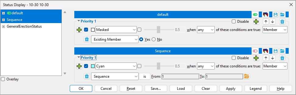
Conditions
(Delete Condition): removes a condition when there are other conditions in that priority, if there are no other conditions in that priority, then
(Add New Condition): Pressing this button adds a new condition. The condition is added to this priority and will be a default condition.
File widgets
File name : The name of a status display file is shown in a banner above the priorities and conditions that are stored in that file. For example, the file name might be default:
default
To delete a status display file from this window, right-click in the file tree (left panel) and choose Delete status. Delete status does not delete a file from your computer, but removes it from this window only.
(active) or
(inactive): You can have multiple files loaded in this window. Each will have its file name displayed in a blue banner. One (1) of these files may be your
(others in gray) or
(others as usual):
If
If
(Save): Lets you save to a file the status information that is under a particular file name banner.
(Open): Lets you open a different file, which on this window will take the place of the file whose
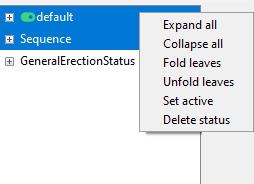
Priority widgets
Disable:
If this box
If the box
/
(Move Up / Move Down) : The priority number changes as you move a priority up or down. Priority 1 is always the first priority applied from a status display file. Changing a priority's number (position) can affect status display. Where conditions in different priorities are true for particular members or materials, the conditions in the higher priority (lower number) are the conditions that control the display.
Display logic
or
or etc. This determines how the stick members and solid members/materials that meet the conditions in the active status file are displayed in the 3D model. If Member and any are selected, members for which at least one of the conditions is true will be hidden (masked) if Masked is selected. If a color is selected, members for which at least one of the conditions is true are displayed in that color.
Opacity lets you make solid members translucent. It applies only when Member is the item to be displayed with the selected opacity. Opacity does not apply to members in stick form. The opacity of members can be set with a slider or by typing a number between 0.1 and 1.0. An opacity of 0.1 makes the status display color nearly invisible, so that you can easily see through the color-coded item. An opacity of 1.0 makes the status display color entirely opaque.

any or all or none: This is the display logic function.

Any will apply the color/mask if any of the conditions in the priority in which you are working in is true for a member/material in the model.
All will apply the color/mask only if all of the conditions in this priority in which you are working in is true for a member/material in the model.
None will apply the color/mask if none of the conditions in this priority in which you are working in is true for a member/material in the model.
Note: For a priority with only one condition, any and all will give the exact same results.
Member or Ends or Left or Right . The display item that is to be color coded or Masked.
Member results in the entire member being color coded, masked or etc. when the status condition is true for the left/right member end or true for the member as a whole. It should also be used for most bolt , weld , hole or material status conditions. Masked and the Opacity slider only apply to members.
Ends results in both ends of the member being color coded when the status condition is true for both ends of a member or true for the member as a whole. Only one end of the member is color coded if the condition is true for only that one end of the member.
Left results in the left end of the member being color coded when the status condition is true for the entire member or true for the left end of the member.
Right results in the right end of the member being color coded when the status condition is true for the entire member or true for the right end of the member.
Special cases: For a bolt , weld , hole or material status condition, selecting Member results in bolts or welds or holes or materials being color coded or etc. You may not get any results when you select Ends or Left or Right for such conditions. It is generally best to select Member when you want to color code bolts, welds, holes or material.
If User and Site Options > Modeling >
Members/materials in your current erection view (as well as in views you subsequently Open ) will now be color coded, isolated or masked per the conditions that are in each Priority that is defined in the active status display file .
The status display toggle will be set to on (
" ![]() Overlay " (when checked) displays one priority at a time. When you select a priority, either from the tree on the left or from inside the window itself, all other priorities collapse.
Overlay " (when checked) displays one priority at a time. When you select a priority, either from the tree on the left or from inside the window itself, all other priorities collapse.
 (or the Enter key) closes the Status Display window . The Status Display window will remember the status display file settings that were most recently entered until you exit Modeling.
 (or the Esc key) closes this window.
The status display toggle will be
If this window was opened for Detail Erection Views , that operation will be cancelled.
 automatically resets this window to those settings that were loaded when this window was opened.
 can be used to save all of the status display files shown on this window to any folder you like. You can even create a new folder for the files.
If Status Display detects that you will overwrite a file of the same name and that file is different than the file shown on this window, you are prompted to overwrite or not.
By default, Save... accesses the
conf_status folder, you are not limited to saving the file(s) into that folder.
 adds one or more new status display file(s) to this window as follows:
1 . A selection dialog opens to the
2 . Select one or more file(s) that you want to load.
3 . The file(s) you selected are added to the file(s) that were already shown on this window.
Also see: Delete Status Configuration (a utility function)
![]() removes all status display files that are shown on this window and reloads the default status display file.
removes all status display files that are shown on this window and reloads the default status display file.
 applies the active status display file's status settings to your current view in the 3D model, but does not close this window.
Since this window remains open after you press Apply, you can make changes to this window and press the Apply button again to see what effect your changes will have on the model.
 provides a color-code key for the active status display file . The legend correlates which colors and priorities are assigned to which conditions. The legend window remains open even after you close the Status Display window. A Status Display Legend icon can be added to a toolbar in Modeling to give you this same functionality without your having to open this window.
|
| The file name of the active status display file summarized in this legend is "Plate Thickness." Priority 1 colors plate material cyan. Priority 2 colors plate material orange. The OK button closes the legend. |
- Status Display check box can be used outside of this window to turn status display on or off ( or ).
- Within a priority , all conditions are acted on by the same display logic . The following example has two conditions. Since all is selected, both conditions have to be true for a member in order for status display to color code that member.
- This example of a status priority would, since all is selected, color code members that have both an auto standard connection and an end plate connection.
- This priority would find two potentially overlapping situations:
- Beams with an end plate on one end and an auto standard connection on the other.
- Beams with auto standard end plates on either end or both ends.
- If you were to change Member to Ends, only those beam ends with auto standard end plates would be color coded cyan.

