A broad range of options to fine-tune your experience using SDS2. Options on this window can apply to you alone (user options) or to your entire site (site options). Settings marked with an asterisk ( * ) require you to exit the program to activate the preference change, unless noted otherwise.
UI theme*:Light or Dark. This changes the color scheme of Home, the Modeling and Drawing Editor environments, tool windows, progress bars, etc. This does not change the Modeling background colors, the Drawing Editor background colors, or other such color settings.
Light
Dark
Select Light if you want the user interface to show dark characters and icons on a light background.
Select Dark if you want the user interface to show light characters and icons on a dark background.
Job/fab selection method: Prompt or Last used
Prompt: The next time you open SDS2, you will be prompted to select a Job. See beginning a Job.
Last used: The next time you open SDS2, the same job that was selected the last time you closed SDS2 will automatically be selected.
Lightning Role Configuration*: Blank or the file name of the role configuration that you want to automatically load when you start up Modeling or Drawing Editor. The Customize Interface window configures the roles that reside in a role configuration file, and you can choose these roles while in Modeling or Drawing Editor by using the role switcher.
If this is blank, the default role configuration is automatically loaded when you launch Modeling.
To enter a configuration file name, you can type its name (if you know it), or you can press the file cabinet browse button ( ) and double-click any role configuration file name that is on the list.
* You must start a new Modeling or Drawing Editor session in order to have the file selected here applied to that environment.
Auto switch to selection context ribbon page: or .
If this box is checked ( ), when you perform an operation that causes the selection context page to appear, you automatically switch to that ribbon page. For example, a Members selection page appears on the ribbon when you perform an operation that requires the selection of a member.
If the box is not checked ( ), the ribbon will not switch to the selection context page automatically.
Auto switch to point location context ribbon page: or .
If this box is checked ( ), when you perform an operation that causes the Locate page to appear, you automatically switch to that ribbon page. For example, when you add a construction line in Modeling, a Locate page appears on the ribbon.
If the box is not checked ( ), the ribbon will not switch to the Locate page automatically.
* You must start new Modeling or Drawing Editor sessions to see the change applied to those environments.
Quick access sidebar icon size*: Small or the Large. This changes the size of tool icons appearing on the quick access feature of the Modeling and Drawing Editor environments. It does not affect the size of the icons on the ribbon.
Select Small for small tool icons.
Select Large for large icons.
Also see: Image size (option to change a tool icon size on the ribbon)
* You must start new Modeling or Drawing Editor sessions to see the change applied to those environments.
Language to use*:Default or English or English (EuroCode) or French or English (IS800) or Japanese or Spanish. Since this is a user option, it is tied to the user name that you log in under, and the choice that you make here will not affect users who have different login names.
Default applies the language that has been set for Language to use under the Site section.
English sets English as the language as described above. Technical terminology is consistent with AISC nomenclature.
English (EuroCode) sets English as the language. Technical terminology is consistent with Eurocode nomenclature. This should be the language when the Connection design method is set to Eurocode 3 UK.
English (IS800) sets English as the language. Technical terminology is consistent with IS800 nomenclature. This should be the language when the Connection design method is set to IS800-2007.
Disk space alert at (MB): The amount of space (in megabytes) remaining in the repository for your current Job at which you wish to begin receiving a warning message telling you that your disk space is low.
Reset stored window positions: SDS2 saves the positions of many windows. For example, if you moved a rectangular plate edit window to one side of your computer screen when reviewing the settings of the plate, then double-clicked on a different rectangular plate to review its settings, the second rectangular plate's window opens in the same place where you moved the first rectangular plate window. This occurs even if you exited Modeling and restarted in the meantime. To restore the default locations of windows, do the following:
1. Press the Reset stored window positions button.
2. An OK-Cancel dialog opens. Press the OK button to reset the size and position of all non-open SDS2 windows to their defaults.
Tip: If you perform an operation that normally causes a window to open and that window does not open, try pressing the Reset stored window positions button.
Disable all sounds: or .
If this box is checked ( ), SDS2 will not beep at you. When you attempt to type in an entry that is not allowed, SDS2 substitutes a visual flash for the audible beep.
If the box is not checked ( ), SDS2 will beep, for instance, when you try to make an entry that is not allowed.
Maximize modules on startup*: or .
If this box is checked ( ), Modeling and Drawing Editor will fill your entire computer screen when you launch them.
If the box is not checked ( ), Modeling and Drawing Editor will be a reduced window size that does not fill your entire computer screen when you launch them.
* You must start a new Modeling or Drawing Editor session in order to see the selection made here applied to that environment.
Show SDS2 version number, hostname, and process ID in window title: or .
If this box is checked ( ), system information is shown next to the window's name on the title bar of edit windows, selection dialogs, etc. When Show current job and fabricator in window title is also checked ( ), the Job and Fabricator names will follow the system information.
If the box is not checked ( ), the window's name, etc. will be shown, but not the system information.
Show current job and fabricator in window title*: or .
If this box is checked ( ), the current Job and Fabricator is shown next to the window's name on the title bar of edit windows, selection dialogs, etc. When Show SDS2 version number, hostname, and process ID in window title is also checked ( ), the system information will precede the Job and Fabricator names.
If the box is not checked ( ), the window's name, etc. will be shown, but not the current Job and Fabricator.
Help browser: System or Other. The browser that you choose here is activated whenever you press a Help button in SDS2.
Select System if you want pressing a Help button to launch the your operating system's default web browser.
Select Other and use the Browse button to locate the .exe file for the web browser that you want to launch when you press a Help button. You can also type or paste the file path. An example of a file path is shown below.
"C:\Program Files\Mozilla Firefox\firefox.exe"
Python developer warning level: None or Simple or Verbose. These choices apply when you run a Python parametric that produces an error or an Output-Request Summary.
If None is selected, no Python warnings are displayed to the screen. However, you may still get an alert notification if the parametric cannot complete.
Select Simple if you want short Python warnings displayed on screen.
Select Verbose to open, in addition to the alert, an Output-Request Summary with the Python trace-back message as in previous SDS2 software versions.
Allow on-screen warning lists*: or . These choices apply when the Python developer warning level is set to Simple or Verbose.
If this box is checked ( ), warning lists are displayed on screen.
If the box is not checked ( ), warning lists are not displayed on screen.
Confirm on log out*: or .
If this box is checked ( ), a Log out confirmation dialog will be displayed when you click Home > Licensing > Log out. The dialog warns you that logging out will also end the current session and gives you the choice not to proceed.
If the box is not checked ( ), such a dialog will not be displayed.
Note: choosing Yes, don't ask again on the Log out confirmation dialog will also uncheck ( ) this option.
General > Display settings
Scrollbars active*: or . Scrollbars let you reposition the display of an erection view in Modeling or a drawing in the Drawing Editor by clicking on them.
If this box is checked ( ), scroll bars will be displayed when you next start up Modeling or the Drawing Editor.
If the box is not checked ( ), scroll bars will be turned off when you next start up Modeling or the Drawing Editor.
* You must start a new Modeling or Drawing Editor session in order to see the selection made here applied to that environment. Please note that you can turn the display of scroll bars on/off immediately (without having to start a new session) by using Display Options in Modeling or Display Options for the Drawing Editor.
Tile decorations active*: or . The tile decoration indicates whether a tile is active, inactive, or focused, and presents tile tools.
A tile with a highlighted decoration
A tile with a highlighted border
If this box is checked ( ), tiles will display tile decorations when you next start up Modeling or the Drawing Editor.
If the box is not checked ( ), tiles will not display tile decorations when you next start up Modeling or the Drawing Editor. Instead, they will display borders when hovered or made active.
Overrides:Tile decorations (Modeling) and Tile Decorations (Drawing Editor) in Display Options can be used can override the choice made here.
* You must start a new Modeling or Drawing Editor session in order to have the file selected here applied to that environment.
Hover tile color: The highlight color of the tile decoration or border that has the mouse focus, unless it has been made active.
A tile without the mouse focus has no tile decoration or border highlighting
A focused tile with a highlighted decoration -- gray, in this example
Active tile color: The highlight color of the decoration bar or border of an active window tile.
A tile without the mouse focus has no border highlighting
A focused, active tile has a highlighted decoration -- blue, in this example
Preferred video graphics*:Automatic or OpenGL or DirectX 11 or Software Emulation. The option that you choose here provides the means by which SDS2 communicates with your workstation's graphics card. You should choose Automatic unless you experience issues with graphics when running SDS2 software, such as construction lines that disappear or "jerky" graphics when you zoom or rotate.
Choose Automatic if you want the program to choose among the usable options listed in the table. An option is deemed usable by SDS2 software if it is supported by your workstation's graphics card. Automatic prioritizes the choice of options in the following order:
If usable, OpenGL is chosen when SDS2 software is running on your local workstation.
If the OpenGL is not usable, or if your SDS2 software is running on a remotely accessed Microsoft Windows session, DirectX 11 is chosen if it is usable.
If OpenGL and DirectX 11 are not usable, Software Emulation is chosen.
Choose OpenGL if you experience graphics issues and neither the DirectX 11 nor the Automatic choice remedies them.
Choose DirectX 11 if you experience graphics issues and neither the OpenGL nor the Automatic choice remedies them.
Choose Software Emulation if you experience graphics issues and none of the other selections remedy them. Some operations, such as zooming and panning, may be noticeably slower than OpenGL and DirectX.
* The choice made here will be applied to the next Modeling and Drawing Editor sessions that you start. Current sessions of Modeling and the Drawing Editor are not affected.
General > Input settings
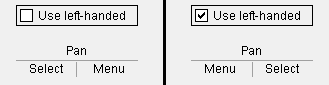
Use left-handed mouse bindings representations*: or .
If this box is checked ( ), bindings for the left and right mouse buttons are shown swapped on your mouse binding reporter. Choose this setting only if you've also swapped the primary and secondary buttons using your mouse driver's software. Otherwise the reporter won't accurately reflect button bindings.
If the box is not checked ( ), bindings for the left and right buttons are not shown swapped on your mouse binding reporter.
Example: The setting on the Use left-handed... option changes the way that mouse binding reporters represent the Select Items bindings.
Also see:Binding indicator layout (also changes the way that 4-button mouse binding reporters display bindings).
Use mouse wheel with 2 or 3 button mouse*: or . This option applies if you are using a mouse with a mouse wheel on a 2- or 3-button mouse. Regardless of your choice here, on a 3-button mouse the mouse wheel always behaves like a middle mouse button (Button number 2).
If this box is checked ( ), you can use the mouse wheel to Zoom In to Pointer (roll forward) or Zoom Out to Pointer (roll backward), or to rotate the view when you Isometric View, or to cycle through details during Sheet Bill Reorder, or to move focus from one widget to the next on a window, or to move scroll bars for a list on a window, or to scroll text in the report viewer. You can also set up the mouse wheel for Next Mode and Previous Mode in Mode Configuration.
If the box is not checked ( ), roll forward or roll backward using your mouse wheel does nothing.
* You must start a new session in Modeling or the Drawing Editor or etc. in order to see the selection made here applied to that environment.
Mouse buttons*: 2 or 3 or 4. Select the number of buttons on the mouse that you use. The number you enter here is the limit of mouse bindings that may be displayed at a time on your mouse binding reporter.
Select 2 if you are using a two-button mouse.
Select 3 if you are using a three-button mouse or a mouse with a mouse wheel.
Select 4 if you are using a four-button mouse.
* You must start a new session in Modeling or the Drawing Editor or etc. in order to see the selection made here applied to that environment.
Binding indicator layout*: 1 or 2 or 3 or 4. This applies when 4 is the selected number of Mouse buttons. Each choice is a mouse button number. Choices made here change the bindings that are shown on the corresponding section of the 4-button mouse binding reporter. You may want to make adjustments to the layout if you have used your mouse driver's software to assign functions to your mouse's buttons.
Note 1: This doesn't assign functions to the buttons of your mouse. To do that, use your mouse driver's software.
Note 2: Only one number can be applied to a section of the mouse binding reporter at a time, so changing the number assigned to one section means swapping it with the number assigned to another section.
* You must start a new session in Modeling or the Drawing Editor or etc. in order to see the selection made here applied to that environment.
Keystroke for button 4*: None or Application or Clear. Documentation in progress. This applies when 4 is the selected number of Mouse buttons.
* You must start a new session in Modeling or the Drawing Editor or etc. in order to see the selection made here applied to that environment.
Activate mode/location tools on: Button press or Pointer entry. This option affects point location icons (which are only active when needed) and mode icons (which have a symbol on them).
If Pointer entry is selected, then moving the mouse pointer ( ) over a mode icon or point location button activates the tool.
If Button press is selected, you must click the mode icon or point location button to activate the tool.
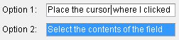
When an entry field is clicked: Place the cursor where I clicked or Select the contents of the field.
If Place the cursor where I clicked is selected when you click a text entry field, then a text insertion bar appears precisely where you click.
If Select the contents of the field is selected when you click a text or numerical entry field, the entire line is selected (highlighted).
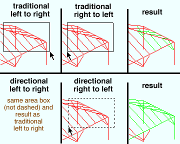
Point selection by area box: Traditional or Directional.
This example is from Modeling. The choice made here also applies to the Drawing Editor.
Select Traditional to cause an area box to behave the same way regardless of whether it is drawn from left to right or right to left. When Traditional is selected, the entire item must be included inside the area box for it to be selected.
Select Directional to cause area boxes to be dashed when drawn from right to left. When the area box is dashed (drawn from right to left), only part of an item needs to be inside of the area box for that item to be selected. In the Drawing Editor, you can also select construction lines when you draw the area box from right to left. When the area box is a solid line (drawn from left to right), the whole item must be included inside the area box for it to be selected.
The up and down arrow keys: Select within combo boxes or Move among controls. This option applies to bothcombo boxes and list boxes.
If Select within combo boxes is selected and a combo box or list box has focus (has a black line drawn around it), the ↑ / ↓ keys open the combo/list box's menu ( ) and can be used to select an item on it. Press the Enter key to apply the selection to the field.
If Move among controls is selected, the ↑ and ↓ keys move focus from control to control on a window in the same way as Tab and Shift + Tab.
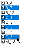
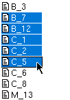
Classic selection lists (7.0 compatibility): or . This affects selection on selection dialogs and on windows such as Hide Items.
If this box is checked ( ), selection works the way it did in v7.0 and earlier versions of SDS2. The following rules apply:
Click an unselected item to select it. Click a selected item to deselect that item.
Drag to select multiple items that are next to each other.
To clear all selections so that you can select a single item, you can press the Clear button. Or you can press the space bar to make the last-clicked item the only item selected.
Tip: If no items are selected and you are on a window where you are permitted to select only one item, double-click selects that one item and closes the window.
If the box is not checked ( ), selection methods are the same as in most programs that work under Microsoft operating systems. The following rules apply:
Click an item to select that item and deselect all other items.
Drag or hold down the Shift key to select multiple items that are next to each other.
Hold down the Ctrl key to select multiple items that are not next to each other.
Double-click one item to both select that item and close the window.
Disable typed dimensions during point location: or .
If this box is checked ( ), you cannot type in a distance and/or angle to constrain second point location. This option is helpful if you use keyboard shortcuts that are bound to number keys during point location.
If the box is not checked ( ), you can type in a distance and/or angle to constrain second point location. The distance and/or angle that you type will be displayed in the status line.
Default construction line color:White or Red or Yellow or Green or Cyan or Blue or Magenta.
Press the button that corresponds to the display color that you want construction lines/circles to be drawn in when you add them in Modeling or the Drawing Editor using Construction Line Add or Construction Circle Add.
Additionally, the choice made here sets the color of construction lines generated during automatic detailing. Changing this color option in the middle of a Job does not retroactively change previously added construction lines/circles, but only affects to-be-added construction lines/circles.
Since construction lines and construction circles are not plotted, the choice you make here will not affect the appearance of drawings on sheets when they are printed.
Model display - cursor: None or Arrow or Crosshair. This option applies to Modeling or the Drawing Editor when the mouse cursor (pointer) is within the drawing area. When located on ribbons, modeling tree, toolbars, etc., the mouse cursor is always an arrow.
Arrow
Crosshair
Select None to cause no mouse cursor to appear in the display area of a view; a mouse pointer in the form of an arrow will still appear for selecting items on windows or on toolbars.
Select Arrow to cause the cause the mouse cursor to appear on-screen in erection views like an arrow ( ).
Select Crosshair to cause the mouse cursor to appear in erection views like a plus sign ( + ).
Point location target: None or Fancy or Small crosshair or Large crosshair.
Fancy
Crosshair
Tools in Modeling and the Drawing Editor: A point-location target appears for certain operations (Construction Line Add, etc.) to show where a point will be placed when you left-click (Locate). The position of the target ( ) depends on where your mouse pointer ( ) is at and the point location option that is active.
Automatically process after modeling operation: Use Site Default or Process and create solids or Process only or Do nothing. Sets the default option for Automatically process after modeling operation in Modeling. This is a user option, which means that it applies to any workstation that you run using your login name.
Automatically process after modeling operation icons in Modeling
Use Site Default
Process and create solids
Process only
Do nothing
Process within member edit*:Use Site Default or On or Off.
Sets the default option for Process within member edit in Modeling (a.k.a. On-the-fly Process). This is a user option, which means that it applies to any workstation that you run using your login name.
Process within member edit icons in Modeling
Use Site Default
On
Off
Prompt to temporarily turn off Z-filtering before some tools: or . When the Z filter on the Point Location Configuration window is checked, all points snap to the Reference Elevation of a plan view. This option allows Z filtering to be temporarily disabled during certain operations.
If this box is checked ( ), and Z filter on the Point Location Configuration window is checked ( ), some operations such as Member Copy and Move/Stretch Members trigger a yes-no window to open with the message: Temporarily turn off Z filtering? Press Yes to temporarily uncheck ( )Z filter for the remainder of the operation. Press No if you want Z filtering to remain turned on for the operation.
If the box is not checked ( ), the option to Temporarily turn off Z filtering? will not appear.
Classic column location for columns added/repeated in plan view: or .
If this box is checked ( ), the top/bottom End elevation of columns added/repeated in a plan view are copied from the previously added column.
If this box is not checked ( ), the bottom End elevation of the column is the elevation (Z global coordinate) of the located point, and the default top End elevation is calculated from the bottom elevation so that the new column is the same length as the previously added column.
Note: This setting does not affect the top/bottom End elevation that is automatically input for the first column that is added in a Modeling session. This only applies to subsequently added/repeated columns. See the step-by-step instructions for Add Column.
Add bolts when matching holes: or .
If this box is checked ( ), you are given the option of adding bolts through the layers of material with the matching holes during a Match Holes operation.
If the box is not checked ( ), you are not given the option to add bolts to matching holes during a Match Holes operation.
Maintain user material and holes relation to vertical column/vertical brace member left end*: or .
If this box is checked ( ), the options for Move material (column) and Move material (vertical brace) will be checked ( ) on their respective edit windows.
If the box is not checked ( ), the options for Move material (column) and Move material (vertical brace) will be not checked ( ) on their respective edit windows.
Modeling > Display settings
Reuse previous session's tile layout: or .
If this box is checked ( ) when you close Modeling, its tile configuration is saved and is automatically reused when you open the next Modeling session, even if you open a different Job.
If the box is not checked ( ) at the time you close Modeling, its tile configuration is not preserved for use in your next Modeling session.
If this box is checked ( ), Display Options > General settings > Rulers is automatically checked ( ) each time you start Modeling.
If the box is not checked ( ), Display Options > General settings > Rulers is automatically unchecked ( ) each time you start Modeling.
* You must start a new Modeling session in order to see the choice made here applied to that environment.
Show user coordinate system indicator at origin when origin is visible: or . This sets the position of the UCS axes which are shown when you click the Toggle UCS icon (so that it is gray) after having set the origin using Set UCS Origin.
If this box is checked ( ), the UCS axes will be positioned at the point of origin set using Set UCS Origin whenever that point is visible in your current view. When that point is not in your current view, the UCS axes will move to the User coordinate system indicator position that you have set below.
User coordinate system indicator position:Lower left or Lower right or Upper left or Upper right. This sets the position of the UCS axes (user coordinate system) which are shown (or disappear) when you click the Toggle UCS icon. It applies to both Modeling and the Drawing Editor.
Lower left places the UCS axes in the lower-left corner of the erection view or drawing.
Lower right puts them in the lower-right corner.
Upper left puts them in the upper-left corner.
Upper right puts them in the upper-right corner.
Show member add options bar*: Disabled or Top or Bottom. Member add option bars are available for the adding of beams, columns, vertical braces, and horizontal braces.
Disabled does not show the member add options bar. The member edit window opens each time you add a member.
Top shows the member add options bar at the top of the modeling space.
Bottom shows the member add options bar at the bottom of the modeling space.
* The next time you start a new Modeling session, the choice made here is applied.
Member isolation solid display type: Solid opaque or Solid transparent or Solid transparent main or Current solid form. This sets the member style that a member or group member is displayed in when in member isolation. This also applies to how materials are displayed in material isolation's edit the material mode and edit views mode.
solid opaque
solid transparent
solid transparent main
Solid opaque or Solid transparent or Solid transparent main results in the member being displayed in the style you select here when it is brought into isolation.
Current solid form displays the member in the solid form it was displayed in before being brought into isolation. If the member was in stick form, it is displayed in solid transparent main form.
Modeling animation duration: Zero (0) or the number of seconds (0.1 to 10) that you want to allow for the animation of view changes in Modeling. The animation shows the transition from one view to the next, which can help you visualize how the view you came from relates to the view you end up in.
An entry of 0 (zero) stops the animation from taking place. View changes are instantaneous.
An entry of 0.5 or 1 or 2 or more seconds causes the animation to last the entered amount of time.
Rotation increment: Any number of degrees from 0.001 to 180.
The number of degrees entered here sets the default Increment on the Rotate Material window, which appears when you Rotate Material, Add Material, or do various other operations.
Level of detail: Any level from highest to lowest. When you zoom out in a Modeling view where members are displayed in any of the three solid forms, there comes a point where the holes and bolts disappear. When you zoom out more, smaller materials followed by larger materials begin to disappear. Finally, the solid members are displayed as if they are in stick form.
The highest level causes all parts of the member to continue to be displayed as you zoom out.
The lowest level makes members lose their detail more quickly as you zoom out. You might want to use this setting for a large Job.
Depth check for new views: or .
If this box is checked ( ), the Add Grid Line operation performed in Modeling uses the depth check limits that are set here. The values entered here are shown on the New Erection View window. If you change the values on the New Erection View window and continue to add more views before ending the Add Grid Line operation, each new view you add will use the values of the last-added view. The next time you invoke Add Grid Line, the defaults will revert back to the values entered here.
If the box is not checked ( ), the Add Grid Line operation uses depth checking limits you currently have set in Modeling.
Snap to surface depth check: The exact distance that you want to see In and Out from the surface that you will be on after you do a Snap to Surface. Only the Out setting applies to Seek to Face.
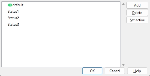
Status display criteria: The status file(s) that are automatically loaded to the Status Configuration list box and the Status Display window when you open Modeling. Press the Define statuses... button to change add files to the list, delete files from the list, and set the active file.
opens the conf_status folder that is used by your current version of SDS2. You can select status display files from that folder or browse to other locations where you have status display files stored. Any files that you select will be shown on the above window.
* You must start a new Modeling session in order to reset the Status Display according to the file entered here.
Prompt to save status display after changes: or .
If this box is checked ( ), you will be given the option to save changes to each status display file when you make a change on the Status Display window and press OK.
If the box is not checked ( ), you are not prompted to save your changes. Your settings will be remembered for the duration of that Modeling session, and you can save those settings by using Save ... on the Status Display window.
Modeling font: The font used to display Modeling text -- for example, piecemarks and section sizes.
Modeling font style: The style (Bold or Bold Italic or Italic or Regular) of the selected Modeling font.
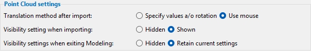
Modeling > Point Cloud settings
Translation method after import:Specify values a/o rotation or Use mouse. This sets the default selection for Translate override on the Point Cloud Manager window.
If Specify values a/o rotation is selected, Specify is the selected Translate override option.
If Use mouse is selected, Mouse is the selected Translate override option.
Visibility setting when importing:Hidden or Shown
If Hidden is selected, Visible will be unchecked ( ) for each scan that is imported. This option could improve performance if your point cloud contains many points.
If Shown is selected, Visible will be checked ( ) for each scan that is imported.
Visibility settings when exiting Modeling:HiddenRetain current settings
If Hidden is selected and Visible is checked ( ) when you exit Modeling, Visible will be unchecked ( ) the next time you open Modeling.
If Retain current settings is selected and you exit Modeling, the Visible setting in your next session of Modeling will be the same as in your previous session.
Modeling > Highlighting options
Settings in this section configure the highlighting that takes place when your mouse pointer ( ) hovers a selectable item in Select Items mode in Modeling.
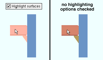
Highlight surfaces (and wire frame if shown): or .
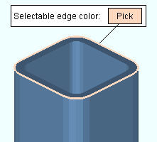
If this box is checked ( ), the surface of a selectable member or submaterial that the mouse pointer ( ) hovers shifts in brightness the percentage that is selected as the Material brightness shift. Selectable holes shift to the color selected for Hole surface. Selectable bolts use the color selected for Bolt surface. If the box for Edged is checked on the Display Options window, those edges are also highlighted.
If the box is not checked ( ), the brightness of the surface of a member or submaterial does not shift when the mouse pointer hovers that item.
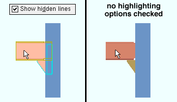
Show hidden lines in 3D wire frames: or .
If this box is checked ( ), a wire frame outline of the entire member or material (including hidden lines) is shown when the mouse pointer ( ) hovers a selectable member or material or bolt or hole. Members displayed in stick form are also highlighted.
If the box is not checked ( ), the wire frame outline that shows 3D hidden lines is not shown when the mouse pointer hovers a selectable member or submaterial. Members displayed in stick form are not highlighted.
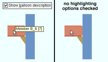
Show balloon description: or .
If this box is checked ( ), a balloon identifying the item (member or submaterial or bolt or hole or weld) is shown when the mouse pointer ( ) hovers that item.
If the box is not checked ( ), a balloon description is not shown when a member or submaterial or bolt or hole is hovered.
Balloon descriptions:
Member:member piecemark and member number. Submaterial:submaterial mark and the member that submaterial is a part of. Bolt: bolt number, whether it is a shop or field bolt, and the member the bolt is a part of. Hole: hole number and the member the hole is a part of. Note: the note's Subject, by whom the note was last edited, and the date & time when it was last edited.
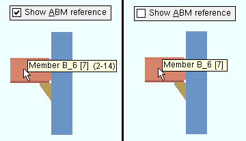
Show ABM reference on balloon descriptions: or . The box for Show balloon description must be checked for this option to apply.
If this box is checked ( ), the ABM page-line (or system ID) is shown in the balloon description for the member or submaterial that the mouse pointer ( ) hovers.
If the box is not checked ( ), the ABM page-line number is not shown in the balloon description.
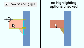
Show member origin: or .
If this box is checked ( ), the origin reference point symbol identifies the 0,0,0 coordinate of the member when the mouse pointer ( ) hovers a member.
If the box is not checked ( ), the origin reference point of the member is not shown when the mouse pointer hovers over a member.
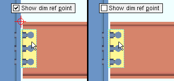
Show material dimension reference point: or . This applies when the selection filter is set to Material.
If this box is checked ( ), the dimension reference point of a material is shown when the mouse pointer ( ) hovers a material.
If the box is not checked ( ), the material dimension reference point is not shown.
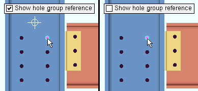
Show hole group reference point: or .
If this box is checked ( ), the hole group reference point is shown when the mouse pointer ( ) hovers a hole that is selectable.
If the box is not checked ( ), the hole group reference point is not shown.
Material brightness shift: The positive or negative (-) percentage (from 0% to 100% of a 30% shift) that you want the material brightness to be increased or decreased by when the mouse pointer ( ) hovers a member or material. The box must be checked for Highlight surfaces to make this percentage apply.
A positive percentage increases the surface brightness.
A negative (-) percentage decreases the surface brightness.
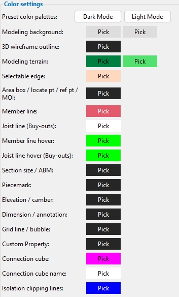
Modeling > Color settings
To change a color: Click the Pick swatch and define a color using your operating system's color picker. If you opened User and Site Options from inside Modeling, any color change made here applies to your current session of Modeling when you press OK to close this window.
Preset color palettes: Choosing Dark Mode or Light Mode changes the default color palette to choices that contrast with dark or light Modeling background colors. This may make items in the Modeling window easier to see.
Warning: If you have previously made choices to color settings, clicking either button will replace those choices with a preset color palette value.
Modeling background: Two color options are available. Setting two different colors creates a gradient background.
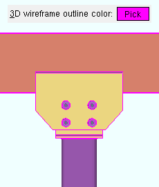
3D wireframe outline: The color of the wire frame outline that appears around members/materials/bolts/holes in Modeling when the box for Edged is checked on the Display Options window.
Modeling terrain: The color you want the terrain to be when the Display Options filter is checked ( ). The first color is applied to the top of the terrain. The second color is applied to the sides of the terrain.
Member line: The color that you want members in stick form to be displayed in, when not selected or hovered. Members in stick form are always displayed in the color green when they are selected.
Joist line (Buy-outs): The color that you want joist outlines to be displayed in when the Display Options filter is checked ( ).
Member line hover: The color that you want a member in stick form to be displayed in when the mouse pointer ( ) hovers it.
Section size / ABM: The color that you want member section sizes and ABM ID to be displayed in when the appropriate Display Options filters are checked ( ).
Piecemark: The color that you want member piecemarks to be displayed in when Display Options > Member piecemarks is checked ( ).
Elevation / camber: The color that you want member end elevations and camber annotations to be displayed in when the appropriate Display Options filters are checked ( ).
Dimension / annotation: The color that you want model dimensions to be displayed in when the appropriate Display Options filters are checked ( ). This also affects temporary annotations, such as point location annotation text.
Grid line / bubble: The color that you want new grid lines and their bubbles to be displayed in. This applies if, in the New Erection View or Edit Erection View window, the Modeling grid line pen color is Use site options.
Custom property: The color that you want custom properties to be displayed in when Display Options > Member custom properties is checked ( ) and when they have been added to an erection view member label.
Connection cube: The color that you want Connection Cubes to be displayed in when Display Options > Connection cubes is checked ( ).
Connection cube name: The color that you want Connection Cube names to be displayed in when Display Options > Connection cubes names is checked ( ).
To change a color: Click the Pick swatch and define a color using your operating system's color picker. If you opened User and Site Options from inside Modeling, any color change made here applies to your current session of Modeling when you press OK to close this window.
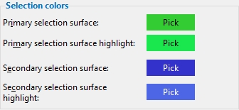
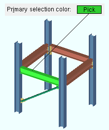
Primary selection surface: The color that you want an item (member, material, bolt, hole) to be displayed in when it is selected in Modeling.
Stick member selection color: Members in stick form are always displayed in the color green when they are selected -- regardless of the color entered here. Also, selected objects in the Drawing Editor are green unless they are already green when not selected.
Primary selection surface highlight: The color you want applied to an already selected item when the mouse pointer ( ) hovers that item. For this color to be applied, Modeling must be in Select Items mode and the box must be checked for Highlight surfaces.
Secondary selection surface: The color that you want an item (member, material, bolt, hole) to became when it is a secondary selection in Modeling. The following table has examples of a few of the operations that require a secondary selection or in some other way used the secondary selection color.
Secondary selection surface highlight: The color you want a secondary selection item to change to when the mouse pointer ( ) hovers that item. For this color to be applied, the item must be a secondary selection, and the box must be checked for Highlight surfaces.
Modeling > Highlighting colors
Settings in this section configure the highlighting that takes place when your mouse pointer ( ) hovers a selectable item in Select Items mode in Modeling.
Also see: The selection filter affects what items (members, materials, bolts or holes) are selectable and therefore what items become highlighted.
To change a color: Click the Pick swatch and define a color using your operating system's color picker. If you opened User and Site Options from inside Modeling, any color change made here applies to your current session of Modeling when you press OK to close this window.
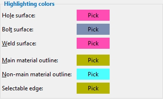
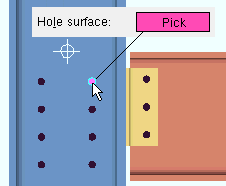
Hole surface: The color that you want the hole surface to be when the mouse pointer ( ) hovers a selectable hole and the box is checked for Highlight surfaces.
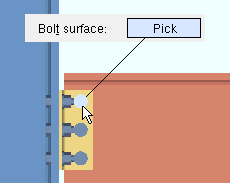
Bolt surface: The color that you want the bolt surface to be when the mouse pointer ( ) hovers a selectable bolt and the box is checked for Highlight surfaces.
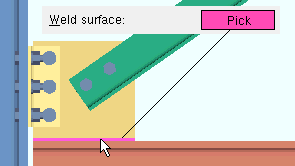
Weld surface: The color that you want the 3D weld to be when the mouse pointer ( ) hovers a selectable weld and the box is checked for Highlight surfaces.
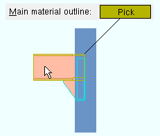
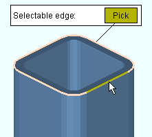
Main material outline: The color that you want the main material outline to be when the mouse pointer ( ) hovers a selectable member or a selectable member main material and the box is checked for Show hidden lines in 3D wire frames.
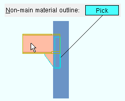
Non-main material outline: The color that you want the main material outline to be when the mouse pointer ( ) hovers a selectable submaterial other than member main material and the box is checked for Show hidden lines in 3D wire frames.
To change a color: Click the Pick swatch and define a color using your operating system's color picker. If you opened User and Site Options from inside Modeling, any color change made here applies to your current session of Modeling when you press OK to close this window.
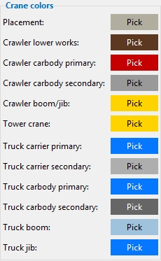
Note: The color will be applied to existing cranes as well as to newly added ones.
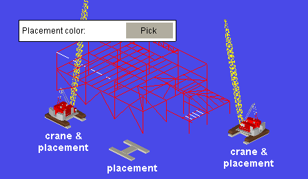
Placement: The color that you want applied to crane placements in Modeling. Crawler cranes, truck cranes and tower cranes all have at least one placement associated with them.
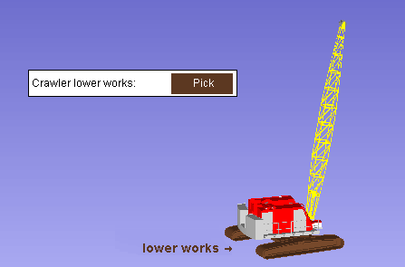
Crawler lower works: The color that you want applied to the lower works of crawler cranes in Modeling. The lower works color will be applied to existing crawler cranes as well as to newly added ones.
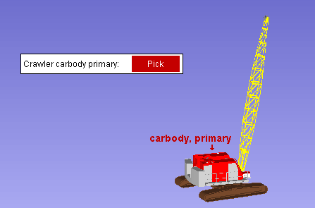
Crawler carbody primary: The color that you want applied to the carbodies of crawler cranes in Modeling. The primary carbody color will be applied to existing crawler cranes as well as to newly added ones.
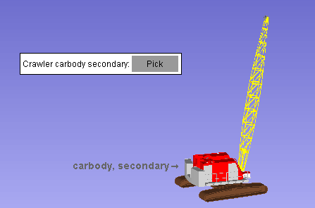
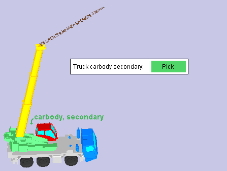
Crawler carbody secondary: The color that you want applied to the carbodies of crawler cranes in Modeling. The secondary carbody color will be applied to existing crawler cranes as well as to newly added ones.
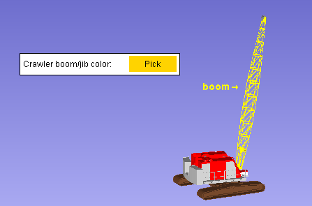
Crawler boom/jib: The color that you want applied to the booms of crawler cranes in Modeling. The boom/jib color will be applied to existing crawler cranes as well as to newly added ones.
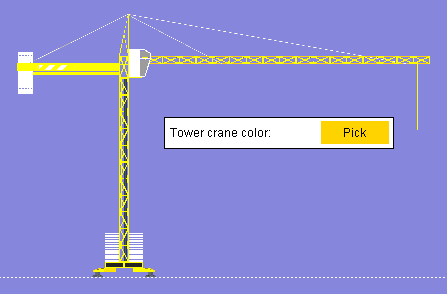
Tower crane: The color that you want applied to the masts and booms of tower cranes in Modeling. The tower crane color will be applied to existing tower cranes as well as to newly added ones.
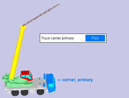
Truck carrier primary: The color that you want applied to the driver compartments of truck cranes in Modeling. The primary carrier color will be applied to existing truck cranes as well as to newly added ones.
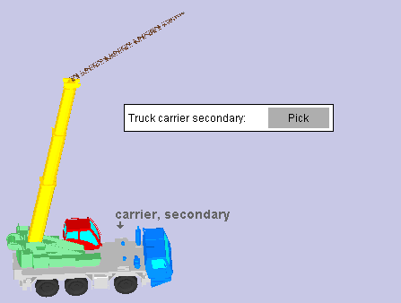
Truck carrier secondary: The color that you want applied to the beds of carriers of truck cranes in Modeling. The secondary carrier color will be applied to existing truck cranes as well as to newly added ones.
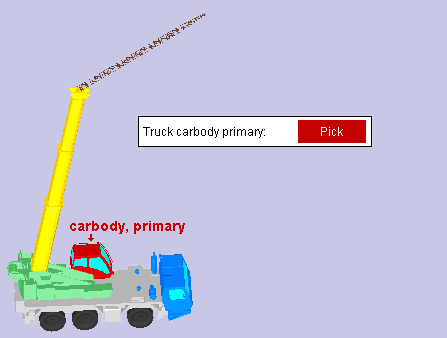
Truck carbody primary: The color that you want applied to the operator compartments of truck cranes in Modeling. The primary carbody color will be applied to existing truck cranes as well as to newly added ones.
Truck carbody secondary: The color that you want applied to the carbodies of truck cranes in Modeling. The secondary carbody color will be applied to existing truck cranes as well as to newly added ones.
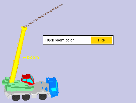
Truck boom: The color that you want applied to the booms of truck cranes in Modeling. The boom color will be applied to existing truck cranes as well as to newly added ones.
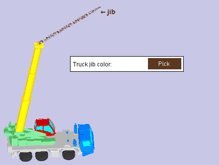
Truck jib: The color that you want applied to the jibs on truck cranes in Modeling. The jib color will be applied to existing truck cranes as well as to newly added ones.
Drawings > Drawing Editor Settings
System dimension rounding: Adjust all on drawing or Adjust all on chain or None. System dimensions are dimensions that are generated during auto detailing. These three options control the rounding that takes place in order to adjust dimensions to the Dimension precision that is set at Home > Project Settings > Fabricator > Detailing > Drawing Presentation.
Adjust all on drawing is the default. Auto detailing calculates a system dimension by first rounding the coordinates for all points in the drawing. This ensures that individual dimensions add up to the overall dimension that is reported in the drawing. However, some individual dimensions may report a value that does not match the value that the Ruler reports for the same dimensioned points.
Adjust all on chain also ensures that individual dimensions add up to the overall dimension. Auto detailing does this by using the first point on a chain of dimensions as the reference point. Single dimensions not on a chain will match the value that the Ruler reports for the same dimensioned points. However, some dimensions on a chain may still be rounded is a way that causes the Ruler to give you different results.
None results in each individual dimension being independently rounded per the Home > Project Settings > Fabricator > Detailing > Drawing Presentation > Primary Dimensions > Dimension precision. It ensures that each dimension in the drawing always matches the value the Ruler would report if you measured the same points.
Warning: Selecting None may result in individual dimensions not adding up to the overall dimension.
User dimension rounding: Adjust all on drawing or Adjust all on chain or None. User dimensions are dimensions that the user places using Add Dimension.
Adjust all on drawing is the default. Add Dimension calculates a user dimension by first rounding the coordinates for all points in the drawing. This ensures that individual dimensions add up to the overall dimension that is reported in the drawing. However, some individual dimensions may report a value that does not match the value that the Ruler reports for the same dimensioned points.
Adjust all on chain also ensures that individual user dimensions add up to the overall dimension when you add the chain of dimensions at the same time. Add Dimension does this by using the first point on a chain of dimensions as the reference point. Single dimensions not on a chain will match the value that the Ruler reports for the same dimensioned points. However, some dimensions on a chain may still be rounded is a way that causes the Ruler to give you different results.
None results in each individual user dimension being independently rounded per the Home > Project Settings > Fabricator > Detailing > Drawing Presentation > Primary Dimensions > Dimension precision. It ensures that each dimension in the drawing always matches the value the Ruler would report if you measured the same points.
Warning: Selecting None may result in individual dimensions not adding up to the overall dimension.
Confirm move/stretch: or . This applies to Move/Stretch in the Drawing Editor.
If this box is checked ( ), Move/Stretch provides a confirmation step with Yes - Nomouse bindings at the end of the operation. Left-click (Yes) confirms that the move or stretch is correct. Right-click (No) lets you re-locate the second point so that the objects are moved/stretched the way you want them.
If the box is not checked ( ), a confirmation step is not included. The Move/Stretch operation is completed when the second point is located.
If this box is checked ( ), the dimension tools listed above provide a confirmation step with Yes - Nomouse bindings at the end of the operation. Left-click (Yes) confirms that the dimension or dimension chain is correct.
For one dimension: Right-click (No) opens the Edit Dimension window. Pressing Cancel on the edit window removes the dimension.
For a dimension chain: Right-click (No) removes the dimension chain.
If the box is not checked ( ), the confirmation step is not included.
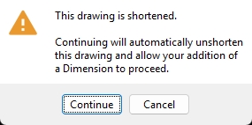
Always ask to unshorten drawings before adding objects*: or . It is recommended that you unshorten drawings before adding objects. By unshortening, you ensure that manually added objects are properly located in the drawing and that your drawing will look correct when you shorten it again. Adding objects in an unshortened drawing also helps to ensure that dimensioning and hatching are correct, and that User-created annotations are correctly preserved if you Detail Members later.
If this box is checked ( ) when you begin to add an object to a shortened drawing, a warning dialog opens. Pressing Continue automatically unshortens the drawing and allows you to proceed with the add operation. Pressing Cancel ends the operation and keeps the drawing shortened.
If the box is not checked ( ), when you begin to add an object to a shortened drawing, you will not get a warning dialog like the one shown above.
* You must start a new Drawing Editor session in order to have your change applied if you opened User and Site Options from Home. If you opened User and Site Options from the Drawing Editor, any change that you make to this option will take effect as soon as you press OK to close this window.
Always show Annotations and Dimensioning window: or .
If this box is checked ( ), the Annotations and Dimensioning window will be shown whenever you Detail Members or Detail Submaterial or Detail Member Groups. The window will open after you have selected the items that you want to detail. Mixed entries are designated in the usual manner.
If the box is not checked ( ), the Annotations and Dimensioning window does not open automatically.
If you want it to be shown, you can press Settings on the selection window.
Always show Detail Erection View Defaults window: or .
If this box is checked ( ), the Detail Erection Views Defaults window will be shown whenever you Detail Erection Views. The window will open after you have selected the erection views that you want to detail. Mixed entries are designated in the usual manner.
If the box is not checked ( ), the Detail Erection View Defaults window does not open automatically. If you want it to be shown, you can press Settings.
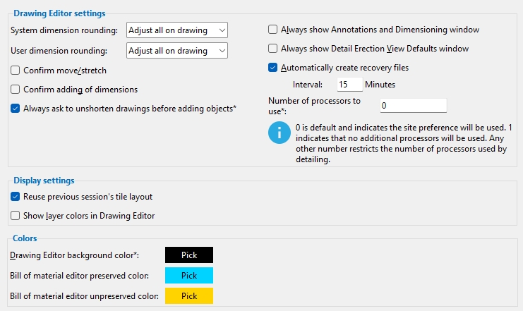
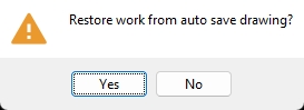
Automatically create recovery files interval: or . This can provide file recovery protection in the event of a crash in the Drawing Editor.
If this box is checked ( ), you can enter a number of minutes (1 to 1440) as the time interval. Opened drawings are automatically saved to a recovery file at that time interval. In the event that the Drawing Editor crashes, unsaved changes you made to that drawing can be recovered when you open it again. The changes stored in the auto saved recovery file can also be recovered by choosing Restore Backup Drawing while you are still working in that drawing. Each time a recovery file is saved, it overwrites the previously auto saved recovery file. When you open a different drawing, the auto saved recovery file is deleted, thus freeing up disk space and preventing project bloat.
The dialog that you may get when you open a drawing that did not close properly due to a crash.
If the box is not checked ( ), recovery files are not created. Unsaved changes cannot be recovered if the Drawing Editor crashes.
Number of processors to use:0 or 1 or etc. A multicore computer chip has two or more independent processor cores on the same chip. SDS2 automatic detailing is able to use all, one, or an allocated number of processor cores. Generally speaking, using more cores makes member, group member or submaterial detailing faster. If using all processor cores causes problems, try limiting the number of cores used by auto detailing.
0 instructs automatic detailing to use the choice that is made to Number to use in the Site section.
1 instructs automatic detailing to use all a single processor core.
2 or3 or etc. limits the number of processor cores that auto detailing uses to the number that is specified.
Example: Your computer has six processor cores, more than the Number to use that is entered in the Site section. Since you want all of your processor cores to be used, you enter the number 6.
Note: This option overrides the choice made to Number to use on the Site screen.
Drawings > Display settings
Reuse previous session's tile layout: or .
If this box is checked ( ), when you close the Drawing Editor, its tile configuration is saved and automatically reused when you open the next Drawing Editor session, even if you open a different Job.
If the box is not checked ( ), when you close the Drawing Editor, its tile configuration is not preserved for use in your next Drawing Editor session.
Show layer colors in Drawing Editor: or . All drawing types have at least one layer. Layer colors can be assigned at the project level at Home > Project Settings > Fabricator > Detailing Drawing Presentation > Colors, and at the drawing level using the Layer Panel.
If this box is checked ( ), layer colors that are turned on in the Layer Panel will be applied to all objects that are on the layer.
If the box is not checked ( ), objects on all layers on Drawing Editor drawings are shown in their usual pen colors, regardless of the layers that they are on.
Drawings > Colors
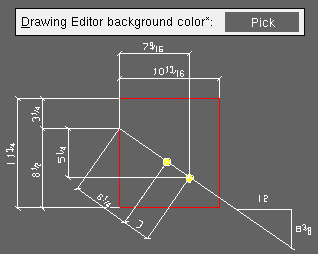
To change a color: Click the Pick swatch and define a color using your operating system's color picker.
* You must start a new Drawing Editor session in order to see the new background color applied.
Drawing Editor background color*: The color that you want applied as the background for drawings when you are working in the Drawing Editor.
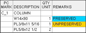
Bill of material preserved color*: The color that you want applied to cells in the bill editor that contain entries made by users.
In this bill of material, PRESERVED and UNPRESERVED are user modified entries. All user modified entries are marked with either the Preserved color or the Unpreserved color.
Bill of material unpreserved color*: The color* that you want applied to cells in the bill editor that were changed to be unpreserved cells. This changing of a preserved cell to an unpreserved cell is done by selecting the information in that cell then right-clicking outside of the cell and choosing Do Not Preserve Cell. Bill of material text that has the Unpreserved color applied to its containing cell is not preserved during detailing of members when the option to Preserve user modified BOM is checked.
In this bill of material, PRESERVED and UNPRESERVED are user modified entries. All user modified entries are marked with either the Preserved color or the Unpreserved color.
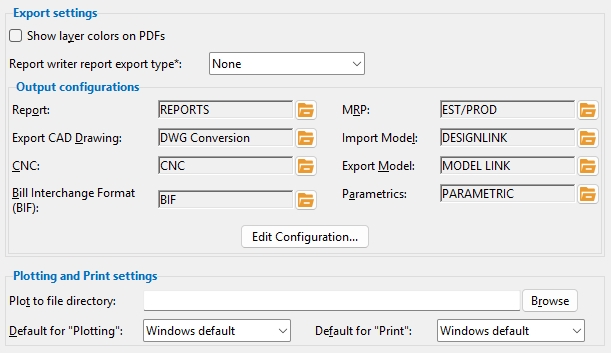
Output > export settings
Show layer colors on PDFs: or . Layer colors can be assigned at the project level at Home > Project Settings > Fabricator > Detailing Drawing Presentation > Colors, and at the drawing level using the Layer Panel. This option controls whether or not layer colors are shown on PDF drawings when you Print PDF and Export PDF Drawing.
If this box is checked ( ), layer colors are shown on PDF drawings when you Print PDF and Export PDF Drawing.
If the box is not checked ( ), layer colors are not shown on PDF drawings.
Report writer export type:None or HTML Table or HTML Absolute or Delimited or SYLK or Excel (Version 2.1). This applies when you Export Report Writer Report and Export report type is set to None on the Destination tab of the Report Writer window.
HTML Table exports the report in the form of an HTML table. When you re-size the browser window used to view the HTML table, each cell in the table expands or contracts to maintain relative column widths. To be properly read by a web browser, the file should be given an .htm or .html extension.
HTML Absolute exports the report in a format that closely matches what you would get if you were to print a formatted report. To be properly read by a web browser, the file should be given an .htm or .html extension.
Delimited exports a comma delimited report in CSV format. When naming the file, give it a .csv or .txt extension. Tip: If you want a file that uses a delimiting character other than a comma, you can set the Export report type to Delimited in the Report Writer and set a different delimiting character.
SYLK exports the report in the Microsoft SYLK (Symbolic Link) format, which is used for interchange of spreadsheet data between applications such as Microsoft Multiplan and Excel. SYLK files normally have a .slk extension.
Excel (Version 2.1) exports a report that can be loaded into the Microsoft Excel v2.1 program and into newer-version Excel programs that are backwards compatible with v2.1. Excel files normally have a .xls extension.
Output > Output configuration
The file cabinet browse button ( ) selects the output configuration file. The Edit Configuration... option (below) lets you, for example, enter the File or Directory you want to output to. Click here for instructions on how to override the output set here.
Import Model occasionally produces a log file. The default DESIGNLINK configuration outputs to Disk.
Export Model sets the Destination on the Export Model window.
Parametrics sets the Directory that opens when you Run Parametric in Modeling. The default PARAMETRIC configuration is set to Disk and targets the output folder in your current version's data directory.
Tip: During output of a file, changing the Configuration resets the choice made here. Changing the Destination applies to that output only.
lets you edit or create a new output configuration.
1. Press the Edit... button.
2. On the selection dialog that opens, select the name of the output configuration file that you want to edit.
3. The Output Configuration Setup window opens. Make your changes to the Destination options on the window, then press the OK button to save your changes.
Output > Plotting and Print settings
Plot to file directory: The path to the file folder that you want print files to be output to when you print to file.
Plot to file directory:
D:/folder/subfolder
You can type in a file path to the file folder that you want, or press the Browse button to open a dialog and select a file folder.
Default for "Plotting": Windows default or Last used. This option applies when you choose Plotting from Home > Export, Drawing Editor, or Modeling.
Windows default sets Plotting to output to the Windows default printer.
Last used sets the printer to be the last one you selected on the Windows Print dialog. If that printer cannot be found, output will be to the Windows default printer.
Default for "Print": Windows default or Last used. This option applies when you Print your current drawing in the Drawing Editor.
Windows default sets Print to output to the Windows default printer.
Last used sets the printer to be the last one you selected on the Windows Print dialog. If that printer cannot be found, output will be to the Windows default printer.
Site options affect all workstations and users in your current version of SDS2.
Site > General Settings
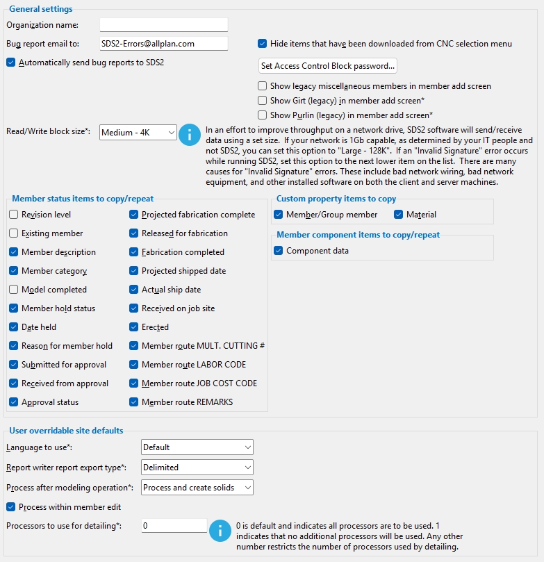
Organization name: The name of your organization.
Effect on your network: Changing this name affects all users on your network (see User vs Site).
Bug report email to: The email address where bug reports are sent when you press an Email button on an error dialog or when the box is checked for Automatically send bug reports. The default entry of SDS2-Errors@allplan.com routes the email to appropriate personnel at ALLPLAN.
Automatically send bug reports to SDS2: or .
If this box is checked ( ), bug reports are sent automatically. Information about the error is sent to the email address entered to Bug report email to.
If the box is not checked ( ), you can press the E-mail button on the error dialog if you want to send a bug report.
Hide items that have been downloaded from CNC selection menu: or . This applies to the selection dialog that opens when you download CNC files from the Computer Numerically Controlled window and you select items by Details or Submaterial.
If this box is checked ( ), items that have been downloaded will not be listed on the selection dialog. You can check the box for Show All to have the downloaded item listed.
If the box is not checked ( ), all potentially downloadable CNC items will be listed on the selection dialog (except those which have been masked using the Hide Items window).
How SDS2 tracks whether items have been CNC downloaded: When you Download from the Computer Numerically Controlled window or Download Material by Location or Download Members by Location, the members are marked as having been Downloaded to CNC in the Member Status Review window and the materials are marked as CNC Downloaded on the General Information window. To change the downloaded status of materials, you can use Mark submaterial CNC downloaded in Change Options. The Update Attributes option CNC downloaded can be used to alter the downloaded status of members, or you can manually uncheck Downloaded to CNC.
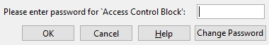
Set access control block password...: Sets a password to prevent users on your network who do not know the password from opening the Access Control window.
1. To set a password, click the Set access control block password... button.
2. The Change Access Control Block Password window opens. Make the appropriate entries to that window to change the password.
3. After you have changed the password here, in User and Site Options, the next time the Access Control window is attempted to be opened for any new Job that was created under that password, the exact password that you just entered must be entered by the user in order to open the window. Shown below is the Password Required window, to which the user must enter the password.
Pressing the Change Password button on this window opens the Change Access Control Password window. Changing the password on that window changes the password for your current Job only.
Note 1: If your current Job was created without an access control block password, then the password you enter here will be applied to that Job. As mentioned above, the password entered here will also be applied to any new Jobs created while that password is active. If you open the Access Control window and clear all entries made to that window, the access control password entered here is applied to that Job.
Note 2: Clearing the Access control block password allows the Access Control window to be opened without entering a password only for subsequently created Jobs or for Jobs subjected to the conditions outlined in note 1.
Note 3: When you do a Project Transfer, the original Job's control block password will be copied along with the rest of the Job. The same is true when you use the Copy Job utility. The Access control block password entered here is applied to a Job only under the conditions outlined in note 1.
If this box is checked ( ), the Girt (Legacy) member type is shown on the Member Type Selection window selection list if the Miscellaneous Steelmember category on that window is also checked.
If the box is not checked ( ), the legacy girt is not shown on the Prompt for Member Type window selection list.
Show Purlin (legacy) in member add screen: or .
If this box is checked ( ), the Purlin (Legacy) member type is shown on the Member Type Selection window selection list if the Miscellaneous Steelmember category on that window is also checked.
If the box is not checked ( ), the legacy purlin is not shown on the Prompt for Member Type window selection list.
Read / Write block size: Large - 128K or Medium - 4K or Small - 1K. When a workstation stores its Jobs on a networked server, a Windows error stating "Invalid Signature" may occur. Such an error may be attributable to network hardware or Windows network settings. Before changing this setting, you should consult the IT experts who maintain your company's Windows network.
Large - 128K makes SDS2 software run faster, but can result in an Invalid Signature Windows network error.
Medium - 4K is the medium block size setting.
Small - 1K is the small block size setting. Theoretically, this setting should prevent an Invalid Signature error.
Site > Member status items to copy/repeat
The Member Status Review options on this screen control the default setting of the Repeat check-boxes on the Member Status Review window.
When an option is checked ( ), the Repeat check-box for that option is checked by default on the Member Status Review window.
When a particular status option is not checked ( ), the Repeat check-box for that option is not checked by default on the Member Status Review window.
Site > Custom property items to copy
Member/Group member: or . This applies to Copy Member operations in Modeling.
If this box is checked ( ), then Copy custom properties will be checked ( ) by default on the Member Copy Information window.
If the box is not checked ( ), then Copy custom properties will be not checked ( ) by default.
Note: For a member added using Repeat, the new member inherits default Edit Properties settings, regardless of the choice made here. For example, if the default Edit Properties setting for a particular member custom property field is blank, that field is set to blank regardless of whether or not an entry has been made to that field for the member being repeated.
Material: or .
If this box is checked ( ), materials that are copied using Material Copy will inherit the Edit Properties settings of the materials they are copies of.
If the box is not checked ( ), newly copied materials that are created using Material Copy will be assigned default custom property settings.
Note: When you Material Copy, there is no way to override the choice you make here.
If this box is checked ( ), all locked ( ) connection design values and custom components on the original member will automatically be copied to the new member you create using Repeat operations. Copy components on the Member Copy Information window is checked ( ) by default when you .
If the box is not checked ( ), all connection design locks will all be unlocked ( ) on the repeated member and custom components will not be copied during Repeat operations. Copy components on the Member Copy Information window is unchecked ( ) by default.
Site > User overridable site defaults
Language to use*: Default or English or English (EuroCode) or French or English (IS800) or Japanese or Spanish.. The choice you make here sets the language for users that share the data directory used by your current version of SDS2 and have their Language to use (per user) set to Default. The selected language is used for menus, status line prompting, edit windows and more.
Default instructs SDS2 to check the Windows default system language.
English sets English as the default language. Technical terminology is consistent with AISC nomenclature.
English (EuroCode) sets English as the default language. Technical terminology is consistent with Eurocode nomenclature. This is probably the best option when the Connection design method is set to Eurocode 3 UK.
English (IS800) sets English as the language. Technical terminology is consistent with IS800 nomenclature. This should be the language when the Connection design method is set to IS800-2007.
* Users who have their Language to use (per user) set to Default will not see the effects of a change of language that you make here until they restart the program.
Report writer report export type:None or HTML Table or HTML Absolute or Delimited or SYLK or Excel (Version 2.1). This applies when you Export Report Writer Report, Export report type is set to None on the Destination tab of the Report Writer window, and Export report type (per user) on User and Site Options > Output screen is set to None.
None exports the report in CSV format. When naming the file, give it a .csv or .txt extension.
HTML Table exports the report in the form of an HTML table. When you resize the browser window used to view the HTML table, each cell in the table expands or contracts to maintain relative column widths. To be properly read by a web browser, the file should be given an .htm or .html extension.
HTML Absolute exports the report in a format that closely matches what you would get if you were to print a formatted report. To be properly read by a web browser, the file should be given an .htm or .html extension.
Delimited exports the report in CSV format. When naming the file, give it a .csv or .txt extension. Tip: If you want a file that uses a delimiting character other than a comma, you need to set the Export report type to Delimited in the Report Writer.
SYLK exports the report in the Microsoft SYLK (Symbolic Link) format, which is used for interchange of spreadsheet data between applications such as Microsoft Multiplan and Excel. SYLK files normally have a .slk extension.
Excel (Version 2.1) exports a report that can be loaded into the Microsoft Excel v2.1 program and into newer-version Excel programs that are backwards compatible with v2.1. Excel files normally have a .xls extension.
Process after modeling operation: Process and create solids or Process only or Do nothing. This sets the default behavior when Automatically process after modeling operation is set to Use Site Default.
Process within member edit: or .
If this box is checked ( ), on-the-fly processing takes place for individual users at your site who have their Process within member edit user preference set to Site.
If the box is not checked ( ), on-the-fly design takes place for individual users at your site who have their Process within member edit user preference set to Site.
Number of processors to use for detailing:0 or 1 or etc. A multicore computer chip has two or more independent processor cores on the same chip. SDS2 automatic detailing is able to use all, one, or an allocated number of processor cores. Generally speaking, using more cores makes for faster member, group member or submaterial detailing. If using all processor cores causes problems, it may be beneficial to limit the number of cores that auto detailing employs. Individual users can set a different Number to use in the Drawings section and thus override the choice made here.
0 instructs automatic detailing to use all processor cores that the computer has available.
1 instructs automatic detailing to use a single processor core.
2 or 3 or etc. limits the number of processor cores that auto detailing uses to the number that is specified.
User vs Site:
User options can be found on this window under all sections except the Site section. User options are personal options that are loaded when you start SDS2 on your network. SDS2 knows at startup which user options to load by looking at your log-in name.
All site options on this window can be found under the Site section. A change made to one of these options affects all workstations and users in your current version of SDS2. If other versions of SDS2 share the same data directory that is used by your current version, they also will be affected. Event Logging Setup in Utility Functions also applies to the entire site.
Example: Suppose that you use SDS2 on another person's computer on your same network, and you log in under your usual log-in name. The result will be that you find yourself using the same user options that you originally set up on your own computer.
Many changes to this window are instantly applied to Modeling or the Drawing Editor when you press OK if you opened this window from inside that program.
A restart of Modeling or the Drawing Editor is always required for options marked * if you opened this window from Home. A restart may not be required if you opened this window from Modeling or the Drawing Editor.
 User and Site Options
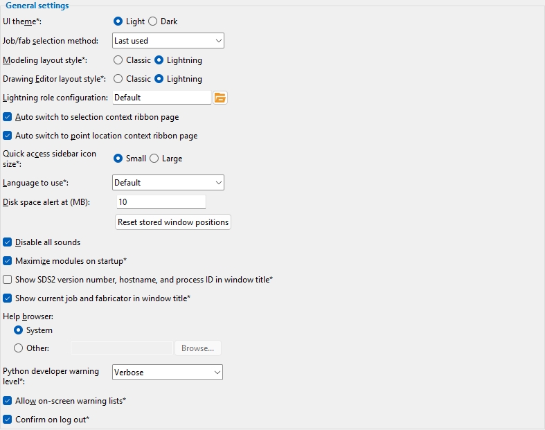
) and double-click any role configuration file name that is on the list.
), when you perform an operation that causes the selection context page to appear, you automatically switch to that ribbon page. For example, a Members selection page appears on the ribbon when you perform an operation that requires the selection of a member.
), the ribbon will not switch to the selection context page automatically.


) over a mode icon or point location button activates the tool.
) and can be used to select an item on it. Press the Enter key to apply the selection to the field.
)


) when you open Modeling.
 Specify values a/o rotation or
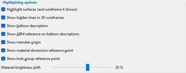
) connection design values and custom components on the original member will automatically be copied to the new member you create using Repeat operations. Copy components on the Member Copy Information window is checked (
) on the repeated member and custom components will not be copied during Repeat operations. Copy components on the Member Copy Information window is unchecked (
) by default.

