Member/material Coordinates (topic)
About member coordinates :
- How member & material coordinates differ
- Examples of wide flange member coordinates
- Each member has its own coordinate system
- Operations that relate to member/material coordinates
Also see :
- Global coordinate system (a related coordinate system)
- Determining a member's left end (a related topic)
- Member/material origin reference point (0, 0, 0 point)
How member & material coordinates differ :
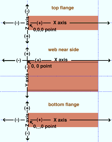
The X axis of submaterial is along the length of the submaterial. The Y axis is the material's depth. The Z axis is toward you and away from you in any view where you can see the material's length and depth (you can see a wide flange, channel or tee's length and depth in a web view).
The MATERIAL axes for beam, column and brace main material will exactly correspond to the MEMBER axes. Their origin reference point will also be the same. For a legacy miscellaneous member , this may or may not be true.
When material is Added to a member (in a full-featured SDS2 program ) so that it comes in with zero (0) rotation around its X, Y and Z material axes, the following will be true: the MATERIAL's left end will be the end closest to the MEMBER's left end; the MATERIAL's X axis will be parallel with the MEMBER's X axis; the MATERIAL's Y axis will be parallel with the MEMBER's Y axis; the MATERIAL's Z axis will be parallel with the MEMBER's Z axis; the origin reference point of the member and material will be on the left ends of the member and material.
When a material has been rotated, however, the above may no longer true. For instance, the reference point (0, 0, 0 point) for a submaterial that has been rotated will not necessarily be on the left end of the material.
In summary: For material that has not been rotated, the X, Y and Z material axes are always parallel with the X, Y and Z axes of the member which that material is a part of. For material that has been rotated an amount other than 360 degrees, the X, Y and Z material and material axes will be different.
page 1 | contents | topics | top
Examples of wide flange member coordinates :
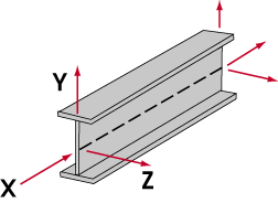
The illustration below shows the X, Y and Z member coordinates for a wide flange beam. The origin point for this coordinate system is the 0, 0, 0 point. It is located at the left end and the top flange center line.

The following illustration shows the member coordinates for a wide flange column or miscellaneous member. Note that the 0, 0, 0 point ( origin reference point ) on this member is not at the top flange, but at the half-depth line (along the neutral axis of the column). When visualizing the coordinates of a column, mentally turn the column on its side so that you are facing its near side and its left end (bottom end) is to your left as shown in the illustration below.

page 1 | contents | topics | top
Each member has its own coordinate system :
The member coordinate system is a local system of coordinates which is drawn in relation to a particular member.
This means that if you rotate that member, its coordinate system will remain the same. The left end does not change when you rotate a member. The X axis is always along the length of the member from left to right. The Y axis runs perpendicular to the X axis along the left end of the member. The Z axis is perpendicular to both the X and Y axes.
Positive and negative directions within this coordinate system are determined with respect to the left end of the member, which includes the point that is the origin of the three axes (the 0, 0, 0 point of the local coordinate system). A force whose direction is from left to right along the X axis is assigned a positive value.
The left end of a member is defined by that member's location in the global coordinate system (not from the viewer's perspective). The left end is fixed, not arbitrary (see determining a member's left end ). In certain views, what will appear from your perspective as the viewer to be the left end of a member will in fact be the right end of the member.
page 1 | contents | topics | top
Operations that relate to member & material coordinates :
For system-generated holes, a " Slot rotation " of ' 0 ' degrees designates that the length of the slot be parallel with the X axis of the material that the hole is on.