The Global Coordinate System (topic)
|
- Global coordinates are fixed
- Identifying global coordinate orientation in views
- Review operations that relate to global axes
Also see :
- How left end relates to global coordinates
- Tools for working in 3D (3D tools relate to global axes)
- Member coordinates (a related coordinate system)
- Origin reference point (relates member & global coordinate systems)
Global coordinates are fixed :
Global coordinates position a member's reference point within the 3D model. Global coordinates do not change as you move from erection view to erection view, although your perspective with respect to this coordinate system does change.
As you move around a model, looking at it from different views, you may sometimes be looking at the model along the Z global axis, at other times along the Y global axis, and at other times along the X global axis. This is analogous to walking around the perimeter of a building and looking at it. Sometimes you look at it from the north, sometimes from the south, and sometimes from the west. As you walk around a building, the coordinate system we call north, south, east and west does not change, nor does the position of that building with respect to north, south, east and west. The only thing that changes is your position.
Members and materials can be placed up to 1 million inches (2,540,000 cm) from the 0, 0, 0 global coordinate.
page 1 | contents | topics | top
Identifying global coordinate orientation in different views :
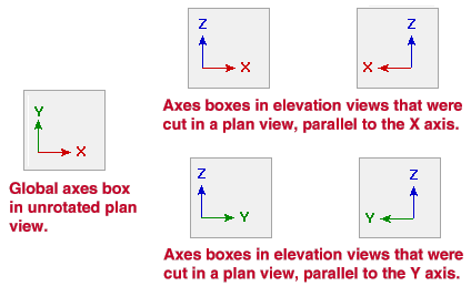
When you are in Modeling , the axes box will inform you of the position of that view with respect to the global coordinate system.

The Z axis is the elevation axis in whatever view you are in.
In a plan view , the X axis is always horizontal with respect to the screen (+ is right, - is left), the Y axis is vertical with respect to the screen (+ is up, - is down), and the Z axis is perpendicular to both the X and Y axes (+ is coming toward you, - is going into the screen).
In a plan view, the global axes are the same as the screen axes . The Y axis is vertical, the X axis is horizontal, and the Z axis (elevation) is coming out from the screen and going into the screen.
In an elevation view , the Z axis (elevation) will be vertical, and either the Y axis or the X axis will be horizontal, depending on which side the structure is being viewed from.
page 1 | contents | topics | top
Review operations that relate to global axes :
The " Reference location X, Y and Z " as reported on the Material General Information window (and which can be changed on this window) is the location of the material's reference point with respect to global axes.
When you set up an isometric view from a plan view, using the => and <= options rotates the view around the 3D model so that your perspective of the global axes changes.
When you Rotate a View , the global axes coordinates of individual members in your 3D model do not change. Only the view changes.
When the Ruler function is used, the program gives the actual distance between the points being measured. If relevant, it also gives the distance from the first point along the X, Y and Z global axes to the second point.
When you change the Relative Depth or Reference Elevation of a view, you are changing that view's position with respect to the 3D model's global coordinate system.
A display current elevation decoration can be added to your toolbar to tell you the reference elevation of a plan view or the relative depth of an elevation view.
For more information on operations that relate to global axes, see tools for working in 3D .