"  Column Plate " connection design locks
| An auto base/cap plate to a beam or joist is designed per " |
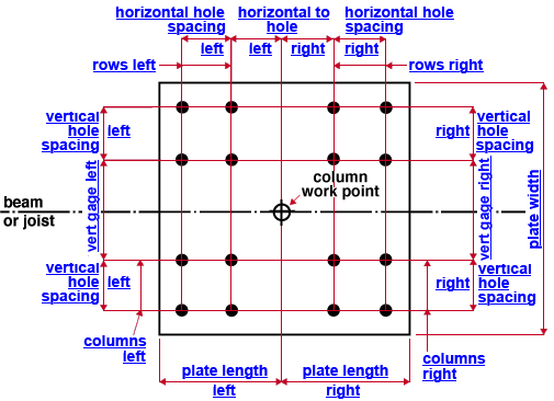
- In the general case (top example), the column work point divides the auto base/cap plate into left and right sections .
- The left and right sections DO NOT have to be mirror images of one another.
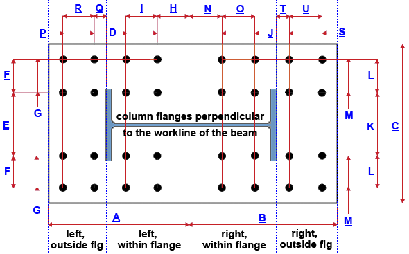
- A special case (second example) is for a column whose flanges are perpendicular to the workline of the beam.
- The plate in the second example is divide into left within flange and right within flange and right outside flange and right outside flange sections.
- The left edge of the base/cap plate is the edge nearest to the left end of the beam or joist.
|
|||
|
" |
|
||
|
|||
|
" ( a special case )  |
|
||
user defined | column review | top
Connection design locks :
| Locks not on the drawings are marked ( not depicted ). |
![]() Column Plate
Column Plate
Plate dimensions (auto base/cap plate to a beam or joist)
Length left ( plate length left ) ( A ):
If this says " Length left - column only ," the auto base/cap plate is connected to by a vertical brace.
Length right ( plate length right ) ( B ):
If this says " Length right - column only ," the auto base/cap plate is connected to a vertical brace.
Plate thickness ( not depicted ):
All bolts
Left bolts (this reads " Left bolts, within flange " for wide flange)
Vertical gage ( vert gage left ) ( E ):
Vertical hole spacing ( vertical hole spacing left ) ( F ):
Columns ( columns left ) ( G ):
Horizontal to hole ( horizontal to hole left ) ( H ):
Horizontal hole spacing ( horizontal hole spacing left ) ( I ):
Right bolts : (this reads " Right bolts, within flange " for wide flange)
Vertical gage ( vertical gage right ) ( K ):
Vertical hole spacing ( vertical hole spacing right ) ( L ):
Columns ( columns right ) ( M ):
Horizontal to hole ( horizontal to hole right ) ( N ):
Horizontal hole spacing ( horizontal hole spacing right ) ( O ):
|
The connection design locks in this section apply to a wide flange, S shape or welded plate wide flange column whose flanges are perpendicular to the workline of the beam. See " Cap Plate ". Warning : If a vertical brace gusset plate has been welded (by connection design ) to the left portion of the auto base/cap plate, the left, outside flange bolt group should be controlled with the " Cap Plate " connection design locks and the locks in this section should be unlocked ( |
|
The connection design locks in this section apply to a wide flange, S shape or welded plate wide flange column whose flanges are perpendicular to the workline of the beam. See " Cap Plate " . Warning : If a vertical brace gusset plate has been welded (by connection design ) to the right portion of the auto base/cap plate, the right, outside flange bolt group should be controlled with the " Cap Plate " connection design locks and the locks in this section should be unlocked ( |
Welds
