The Detailing Symbol Settings window ( Fabricator Settings ) (read-only)
- Settings on this window tell you how the window has been set up for this Fabricator in a full-featured SDS2 program .
- The Fabricator Options that you can review on this window configure the information reported by weld/ piecemark/ bevel/ hole symbols and control the placement of these symbols on automatically detailed member or submaterial details. For example, users of a full-featured SDS2 program can use the equivalent of this window to set up whether or not the weld length will be reported on weld symbols.
Also see :
- Bevel symbols (certain selections on this window affect)
- Weld symbols (certain selections on this window affect)
page 1 | contents | home > project settings > fabricator > detailing > | classic | top
To open Detailing Symbol Settings :
Method 1 : Home > Project Settings > Fabricator > Detailing > Detailing Symbol Settings .
Methods 2, 3 & 4 : In Modeling or the Drawing Editor , choose Settings > Fabricator Settings > Detailing Symbol Settings (classic) or use a keyboard shortcut or click the icon .
page 1 | contents | home > project settings > fabricator > detailing > | classic | top
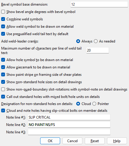
Bevel symbol base dimension: The distance (in the primary dimension " Units " or in other units ) that is to be reported as the longer dimension (" Run " or " Rise ") on a bevel symbol or in the " Bevel " on the Distance Ruler window. If the " Rise " is longer than the " Run ," the value entered here is reported as the " Rise ."
Effect on a full-featured SDS2 program: The entry shown here applies to bevel symbols that are generated when members or submaterial are automatically detailed in a full-featured SDS2 program . It applies in Site Planning when Add Bevel is used or when " Bevel " is reported on the " Angle " tab on the Distance Ruler window.
Show bevel angle degrees with bevel symbol: ![]() or
or ![]() . The selection shown here applies to all bevel symbols (except " Double-sided " bevel symbols) in all drawings that currently exist in your current Job as well as to yet-to-be-created drawings.
. The selection shown here applies to all bevel symbols (except " Double-sided " bevel symbols) in all drawings that currently exist in your current Job as well as to yet-to-be-created drawings.
If the box is checked (
), bevel angle degrees are shown on bevel symbols .
If the box is not checked (
), bevel angle degrees are not shown on bevel symbols.
Combine weld symbols: ![]() or
or ![]() . The entry shown here applies to weld symbols that are generated when members are automatically detailed in a full-featured SDS2 program .
. The entry shown here applies to weld symbols that are generated when members are automatically detailed in a full-featured SDS2 program .
|
If this box is checked (
If the box is not checked (
Allow weld symbol to be drawn on material: ![]() or
or ![]() . The entry shown here applies to any weld symbols that are generated when members are automatically detailed in a full-featured SDS2 program .
. The entry shown here applies to any weld symbols that are generated when members are automatically detailed in a full-featured SDS2 program .
If this box is checked (
If the box is not checked (
Use prequalified weld tail text by default: ![]() or
or ![]() . This affects the default that is set for user-added 3D welds in Modeling in a full-featured SDS2 program , which in turn affects how those welds are depicted on member details.
. This affects the default that is set for user-added 3D welds in Modeling in a full-featured SDS2 program , which in turn affects how those welds are depicted on member details.
If this box is checked (
If the box is not checked (
Add weld-leader cranks: ![]() Always or
Always or ![]() As needed . A weld-leader crank is a node or juncture near the pointer end of a weld leader line. The leader line may bend at the crank, or it may run straight across the crank. A crank on a straight leader line may be identifed by an end point . In a full-featured SDS2 program, system-generated weld symbols are found on member details.
As needed . A weld-leader crank is a node or juncture near the pointer end of a weld leader line. The leader line may bend at the crank, or it may run straight across the crank. A crank on a straight leader line may be identifed by an end point . In a full-featured SDS2 program, system-generated weld symbols are found on member details.
|
'
Always ' instructs automatic detailing of members in a full-featured SDS2 program to generate a crank at a point approximately the length of two arrow heads away from the tip of the arrow head at the end of a weld symbol's leader line. Even if the leader line is straight, a crank will be created, allowing the user of that full-featured SDS2 program to manually bend the leader line at that juncture. In SDS2 software v2015 and earlier, all system-generated weld symbols had cranks.
'
Maximum number of characters per line of weld tail text: In a full-featured SDS2 program, this sets the default value for " Characters per line of symbol tail text " in the Weld Input window when you Detail Members. This value is the maximum length for a line of supplementary tail text measured by the number of characters. The text will wrap to the next line when this length is exceeded. The default value is 20. This value must be greater than or equal to 10 and less than or equal to 50. In a full-featured SDS2 program, you can override the choice made here on a per-drawing basis by editing the weld symbol in Drawing Editor. Enter a different value in the " Characters per line of symbol tail text " field or check the box for " Keep layout symbol tail text as shown " on the Weld Input window.
Allow hole symbol to be drawn on material: ![]() or
or ![]() . The entry shown here applies to hole symbols that are generated when members are automatically detailed in a full-featured SDS2 program .
. The entry shown here applies to hole symbols that are generated when members are automatically detailed in a full-featured SDS2 program .
|
If this box is checked (
If the box is not checked (
Allow piecemark to be drawn on material: ![]() or
or ![]() . The entry shown here applies to piecemarks that are generated when members are automatically detailed in a full-featured SDS2 program .
. The entry shown here applies to piecemarks that are generated when members are automatically detailed in a full-featured SDS2 program .
If this box is checked (
If the box is not checked (
Show paint stripe on framing side of shear plates: ![]() or
or ![]() . This applies when members are automatically detailed in a full-featured SDS2 program .
. This applies when members are automatically detailed in a full-featured SDS2 program .
|

If the box is checked (
If the box is not checked (
Show non-standard hole sizes on detail drawings: ![]() or
or ![]() . This applies to automatically detailed member details only. On submaterial details, non-standard hole sizes are always identified (regardless of the selection shown here).
. This applies to automatically detailed member details only. On submaterial details, non-standard hole sizes are always identified (regardless of the selection shown here).
|
If the box is checked (
If the box is not checked (
Show non-quad boundary slot-rotations with symbol-note on detail drawings: ![]() or
or ![]() . This applies in a full-featured SDS2 program to automatic detailing of member details when "
. This applies in a full-featured SDS2 program to automatic detailing of member details when " ![]() Show non-standard hole sizes on detail drawings " is turned on.
Show non-standard hole sizes on detail drawings " is turned on.
|

If the box is checked (
If the box is not checked (
Call out standard holes with mixed bolt/hole units on details: ![]() or
or ![]() . This applies to member details when the primary dimensioning " Units " are different than the " Bolt diameter " set for Non-moment bolts in Bolt Settings .
. This applies to member details when the primary dimensioning " Units " are different than the " Bolt diameter " set for Non-moment bolts in Bolt Settings .
|
|||||
Definition of standard hole: A standard hole is any round hole that is the standard diameter. Connection design calculates the standard hole diameter from the " Bolt diameter " set for Non-moment bolts in Bolt Settings . For AISC connection design methods, this calculation is done per AISD Table J3.3 or Table J3.3M ( Thirteenth Edition , p. 16.1-105).
If this box is checked (
If the box is not checked (
Designation for non-standard holes on details: Cloud or Pointer . This applies to automatically detailed member details only. On submaterial details, non-standard hole sizes are always identified with clouds. The standard hole size for a Job is based on the " Default non-moment bolt diameter for this job ."
|
' Cloud ' causes a cloud to be drawn around groups of non-standard holes.
' Pointer ' causes a pointer (->) to be drawn to indicate a non-standard hole.
Cloud and note holes having slip-critical bolts on member details: ![]() or
or ![]() .
.
|
The labels shown in this column detail were generated automatically during automatic detailing in a full-featured SDS2 program . Text in the labels matches entries made here, on this window. The entriy made here to " Note line 1 " was "SLIP CRITICAL". The entry made here to " Note line 2 " was "NO PAINT NS/FS". " Note line 3 " was left blank. |
If this box is checked (
If the box is not checked (
page 1 | contents | home > project settings > fabricator > detailing > | classic | top